Specifications
Manuals
Brands
Mestek Manuals
Heater
SEPARATED COMBUSTION GAS FIRED PROPELLER UNIT HEATER
11
12
13
14
15
16
17
18
19
20
16
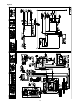
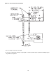
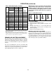
Figure 10 -
V
er
tical Intake/V
ent Installation
*
Size according to expected sno
w depth.
**
If e
xcessive condensation de
velops
, a dr
ip leg with a condensate drain ma
y be required.
Insulating the pipes
ma
y eliminate the problem.
1
...
...
14
15
16
17
18
...
...
32