
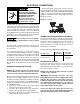
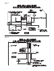
Specifications

12
VENTING FOR POWER VENTED (CATEGORY III) UNIT HEATERS
The venting system for these appliances shall terminate
at least four feet (1.2m) below, four feet (1.2m) horizontal
from, or one foot (0.3m) above any door, window, or
gravity air inlet into any building.
Through the wall vents for these appliances shall NOT
terminate over public walkways, or over an area where
condensate or vapor could create a nuisance or hazard
or could be detrimental to the operation of regulators,
relief valves, or other equipment.
The vent pipe equivalent length must be 5 feet (1.5 m)
minimum and must not exceed 50 feet (15.2 m).
Equivalent length is the total length of straight sections
PLUS 15 feet (4.6m) for each 90 degree elbow, 8 feet
(2.4 m) for each 45 degree elbow, and 10 feet (3.0m) for
the vent cap. An elbow should never be attached
directly to the venter!
Maintain 6 inch (152mm) between vent pipe and
combustible materials. A minimum of 12 inch (305mm)
of straight pipe is required from the venter outlet before
installing an elbow in the vent system.
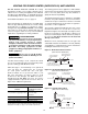
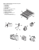
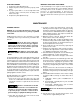
Figure 9 - Horizontal Left Vent Position
(Rear View of Unit Heater)
Figure 10 - Horizontal Right Vent Position
(Rear View of Unit Heater)
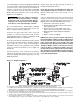
Figure 11 - Vertical Vent Position
(Side View of Unit Heater)
All unit heaters must be vented! All venting
installations shall be in accordance with the latest
edition of Part 7, venting of Equipment of the National
Fuel Gas Code, ANSI Z223.1, or applicable provisions
of local building codes for natural or power vented units.
For Canadian installations, also see page 13.
Power vented units are designed to be used with single
wall vent pipe utilizing horizontal or vertical venting
arrangements (see Figures 9, 10 and 11). These
arrangements may terminate external to the building
using either a single wall or double wall (Type B)
vent. See Figures 9 thru 16 for special installation
requirements regarding these venting conditions.
CARBON MONOXIDE!
Your venting system must not be blocked by
any snow, snow drifts, or any foreign matter.
Inspect your venting system to ensure
adequate ventilation exists at all times! Failure
to heed these warnings could result in Carbon
Monoxide Poisoning (symptoms include
grogginess, lethargy, inappropriate tiredness, or
fl u-like symptoms).
Do not use a type B (double
wall) vent internally within the building on our
power vented units!
If double wall venting is used, components which
are UL Listed and approved for Category III positive
pressure venting systems MUST be used.
A Briedart Type L, Field Starkap or an equivalent
vent cap must be supplied by the customer
for each power vented unit. The vent pipe
diameter MUST be as specified in Table 1 (“D”
Dia. Flue Opening). A reducer must be field
installed for 100 through 175 MBH Unit Sizes.
All 300 through 400 MBH Unit sizes are factory
equipped with the required flue increaser. Refer to
Figure 10 for additional requirements.
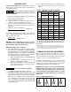
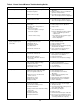
Vent Systems - Termination Clearance Requirements*
Minimum Clearances for
Structure Termination Locations
4 feet below
Door, window or any gravity air inlet 4 feet horizontally
1 foot above
Forced air inlet within 10 ft. 3 feet above
Adjoining building or parapet 6 feet
Adjacent public walkways 7 feet above grade
* If the vent terminal is to be installed near ground level, the vent
terminal must be positioned at least twelve inches above the maximum
anticipated snow depth (see page 13 for Canadian requirements).
Tee With Drip Leg &
Cleanout Cap At Lowest
Point Of Vent System (Typ.)
D4072
To Horizontal Flue
Vent Termination
Reducer/Increaser
Where Applicable
Power Venter
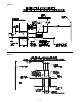
D4071
AIR FLOW
Power Venter
Tee With
Drip Leg &
Cleanout Cap
To Vertical Flue
Vent Termination
Reducer/Increaser
Where Applicable
Power Venter
Tee With Drip Leg &
Cleanout Cap At Lowest
Point Of Vent System (Typ.)
D4073
To Horizontal Flue
Vent Termination
Reducer/Increaser
Where Applicable