
User manual


Table Of Contents
2.GettingStarted
NIC990lUserManual11
2.1.2 Connecting to a Power Supply
The camera does not include an On/Off switch. The equipment is simply connected to/
disconnect from a power source to power on/off. Users can power the equipment on by one of
the following options:
• 24 VAC: Connect the power input terminal block of the equipment to a 24VAC power
source.
• POE+: Connect the equipment via a category 5/5e or higer UTP/STP cable to a POE+
(802.3at) compliant router or Ethernet switch.
TipCautionWarning
Note
Please make sure the power source is AC 24V / PoE+. Although the camera can be powered via
a PoE+ connection, the PoE+ power source won’t be able to drive the camera with its equipped
heater being operating simultaneously. Users are supposed only to supply the camera with AC 24V
continuously for the heater inside the camera to operate.
2.1.3 Deployment
There are many different ways that you can connect the camera to your network, depending on
your applications requirements. You should always set the camera’s network settings according
to your network congurations. The following diagrams depict some typical applications with
guidelines on network settings. For more information on network settings, always consult with
your network administrator or ISP as required.
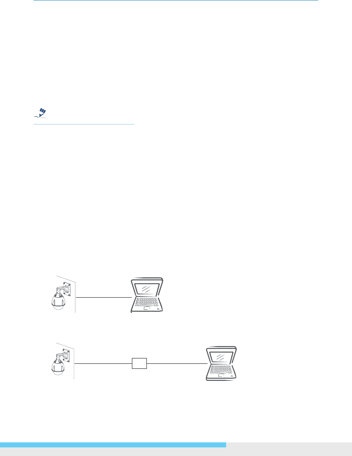
Type 1: Direct Connection to a PC
Directly connect the RJ-45 cable of the camera to a PC.
To extend the connection length, you should use an RJ-45 female/female coupler to connect two
category 5/5e UTP/STP cables together.
RJ-45 Coupler