
User Guide


MESHTEK-H52E
ilumi solutions, inc. www.ilumisolutions.com http://www.ilumi.co/ P a g e 7 | 13
3. PHYSICAL DIMENSIONS
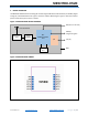
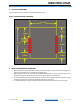
Figure 4 shows the size and footprint for MeshTek-H52E module
Figure 4: MESHTEK-H52E FOOTPRINT
4. LAYOUT AND MOUTING GUIDELINES
We recommend 2 or more layers for the Carrier Board (Host PCB). The top side shall be mostly ground.
Signal routing shall be done in the bottom or middle layers.
When laying out the Carrier board for the MESHTEK-H52E module, the areas under the antenna and
shielding connections should not have signal traces, ground planes or exposed vias.
For the best Bluetooth range performance, the antenna area of module shall extend 6.3mm outside
the edge of Carrier Board or 6.3mm outside the edge of a ground plane.
For the best Bluetooth range performance, keep all external metal away from the antenna area.