ViewPoint Professional Series VPx Sensor User Manual Document No. DV3412 September 24, 2021 Rev.
VPx Sensor User Manual 2 Contents 1.0 Figures ............................................................................................................................................... 3 2.0 Introduction ...................................................................................................................................... 4 2.1 FCC NOTICE ................................................................................................................................... 5 2.
VPx Sensor User Manual 3 1.0 Figures 3-1 VPx Sensor with LCD ............................................................................................................................... 7 3-2 VPx Sensor with LCD Buttons.................................................................................................................. 7 Table 3-1 Input Types....................................................................................................................................
VPx Sensor User Manual 4 2.0 Introduction The VPx sensor integrates with Mesa’s ViewPoint 1.1 or above software solution. The VPx 900 MHz sensor operates in a 902 to 928 MHz range. This device complies with Part 15 of the FCC Rules. Sensor operation is subject to the following two conditions: (1) this device may not cause harmful interference, and (2) this device must accept any interference received, including interference that may cause undesired operation. Ex.
VPx Sensor User Manual 5 2.1 FCC NOTICE WARNING This equipment has been tested and found to comply with the limits for a class B digital device, pursuant to part 15 of the FCC Rules. These limits are designed to provide reasonable protection against harmful interference in a residential installation. This equipment generates, uses and can radiate radio frequency energy and if not installed and used in accordance with the instructions, may cause harmful interference to radio communications.
VPx Sensor User Manual 6 2.2 Industry Canada This device contains licence-exempt transmitter(s)/receiver(s) that comply with Innovation, Science and Economic Development Canada’s licence-exempt RSS(s). Operation is subject to the following two conditions: (1) This device may not cause interference. (2) This device must accept any interference, including interference that may cause undesired operation of the device.
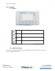
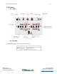
VPx Sensor User Manual 7 3.0 Features 3.1 Buttons 3-1 VPx Sensor with LCD Cycle Used for cycling through screens or menu options Select Select menu option Previous / Next Return to previous screen or Next option Mute Mute local Audio Visual Alarms 3-2 VPx Sensor with LCD Buttons 3.2 Audio Visual Alarm VPx Sensor has local Audible Visual alarms to notify individuals of sensor alarm states even with no access to the Viewpoint software. Mesa Labs, Inc. 12100 W.
VPx Sensor User Manual 8 LED for Visual Alarm To mute local Audible and/or visual alarms, press the button to silence the local alarm ONLY.* To perform corrective action for alarm states, do so in the ViewPoint software. *Note: This is only possible when the sensor is in an alarm state. It cannot be used to mute future alarms. Muting the sensor with the button on the device will only mute that alarm.
VPx Sensor User Manual 9 4.0 Menus 4.1 Home 4-1 Home Screen 4.2 Min Max To get to the Min-Max screen, start at the Home screen, Press Step 1 Result x1 Min Max Screen Table 4-1 Access Min Max Menu Procedure Mesa Labs, Inc. 12100 W. 6th Avenue Lakewood, CO 80228 USA Tel: 303-565-2724 monitoring.mesalabs.com techsupport@mesalabs.
VPx Sensor User Manual 10 4-2 Min Max Screen 4.3 Clear Min Max Press Step 1 Result x2 Step 2 x1 Step 3 x1 Option Screen Select Clear Min Max Confirm Clear Min Max Table 4-2 Clear Min Max Procedure 4.4 Diagnostics Menu The VPx sensor has onboard diagnostic capabilities that can assist in a variety of setup or troubleshooting scenarios.
VPx Sensor User Manual 11 4-3 900 MHz Diagnostics Screen 4-4 Wi-Fi Diagnostics Screen Mesa Labs, Inc. 12100 W. 6th Avenue Lakewood, CO 80228 USA Tel: 303-565-2724 monitoring.mesalabs.com techsupport@mesalabs.
VPx Sensor User Manual 12 5.0 New Battery Note: Use only 3 3.6 V Lithium-Ion Batteries (P/N 166112). 5.1 Battery Replacement To replace the (3) 3.6V lithium batteries in the VPx sensor, press down on the two recessed areas on the rear plate of the sensor and pull back the back cover to open the unit. 5-1 VPx Sensor Top and Back View Mesa Labs, Inc. 12100 W. 6th Avenue Lakewood, CO 80228 USA Tel: 303-565-2724 monitoring.mesalabs.com techsupport@mesalabs.
VPx Sensor User Manual 13 5-2 VPx Sensor Internal View (Back Cover Removed) After replacing the batteries, it is necessary to reset the battery level indicator. To reset the battery level indicator, start from the Home screen: Press Step 1 Step 2 Step 3 Step 4 Result x2 x2 x1 x1 Option Screen Move up to “New Battery” New Battery Confirmation “Confirm” New Battery Table 5-1 Reset Battery Level Display Procedure (LCD) Mesa Labs, Inc. 12100 W.
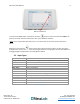
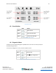
VPx Sensor User Manual 14 6.0 Ports The VPx Sensor has 4 I/O ports that can accept 2 channels of RTD temperature probes, 2 channels of general-purpose analog probes: 4-20 ma, 5v, 10v, 20v and 30v, a discrete switch/contact input, and one I2C input for a Humidity/Temperature probe.
VPx Sensor User Manual 15 Connections for 4-20 ma, 5v, 10v and 30v Inputs: Channel 1&2 Pin 1 2 3 4 Description Not connected 4-20 ma in; 5,10,20,30v in Ground Not connected Table 6-3 VPx Sensor 4-20 ma, 5v, 10v and 30v Inputs 7.0 Specs All specs below are estimated ranges for the particular inputs. Please refer to the probe specific documentation for the exact ranges and tolerances. 7.
VPx Sensor User Manual 16 8.0 LCD Icon Legend Icon Description Alarm, above/below alarm limits Alarm, limits (Min-Max screen) Battery Full Battery 2/3 Battery 1/3 Battery Low A/C Power connected Home Settings Link broken Link connected Min Max Fast Transmit Memory 1/3 full Memory 2/3 full Memory full Mesa Labs, Inc. 12100 W. 6th Avenue Lakewood, CO 80228 USA Tel: 303-565-2724 monitoring.mesalabs.com techsupport@mesalabs.
VPx Sensor User Manual 17 Sound On Sound Muted Icon for Min/Max screen Motion (not moving) Motion (Moving) Contact No Contact Door Open Door Closed Signal Quality (no signal) Signal Quality – Poor Signal Quality – Fair Signal Quality – Good Signal Quality – Best Table 8-1 LCD Icon Legend Mesa Labs, Inc. 12100 W. 6th Avenue Lakewood, CO 80228 USA Tel: 303-565-2724 monitoring.mesalabs.com techsupport@mesalabs.
VPx Sensor User Manual 18 9.0 Operation Compatibility 9.1 DS-VP-PRO-900-S Radio Network Compatibility The DS-VP-PRO-900-S supports two radio networks: “ViewPoint G5 Compatibility” and “CheckPoint G4 Compatibility”. The sensor can be configured for either mode using the VPx Configuration Utility. To use the utility to set the mode, first click the “Read All” button, navigate to the Wi / Radio tab and select an option in the “Compatibility Mode” field. Click the “Apply Radio + Flexband Config” button. 9.
VPx Sensor User Manual 19 For “CheckPoint G4 Compatibility “ (G4 Compatibility Mode) MHz): Hop Table Frequency Range MHz Standard (0) Full (1) Low (2) High (3) 906.000 to 924.000 903.000 to 926.000 903.000 to 913.325 914.773 to 926.000 (903.000 to 926.000 Num Transmitting Channels 58 58 58 58 Make sure to select the hop table that the radio network is using. The default hop table used is 0 – Standard.