AP1000 Beta Test Safety Precautions Chapter 2 Installing AP300 This chapter describes how to install and configure an AP300. It contains the following sections: Safety Precautions Unpack the AP300 Determine Power Requirements Installation Requirements Install the AP300 Check AP300 LED Activity Check AP300 LED Activity Where to Go From Here Safety Precautions IMPORTANT—Read and follow the regulatory instructions in Appendix B before installing and operating this product.
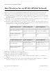
AP1000 Beta Test Best Practices for an AP300/AP1000 Network Best Practices for an AP300/AP1000 Network Read this section if you have both AP1000 and AP320i active simultaneously on the same network. The following best practices should be followed to get optimal performance from such a mixed network. AP320i and AP300 are interchangeable and fully compatible to share a virtual cell. It's like having two AP300s with different antennas.
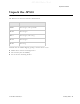
AP1000 Beta Test Unpack the AP300 Unpack the AP300 The AP300 series has five models as shown below. Model Radios PSM3x One a/b/g/n, one spectrum AP320 Two a/b/g/n AP311 One a/b/g/n, one a/b/g AP310 One a/b/g/n AP302 One a/b/g Confirm that the AP300 shipping package contains these items: AP300 with attached mounting bracket Six antennas (four for PSM3x) Screws for the mounting bracket © 2010 Meru Networks, Inc.
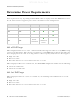
AP1000 Beta Test Determine Power Requirements Determine Power Requirements Power requirements vary, depending on which AP300 radios are deployed and what MIMO mode is used. See the chart below for supported power sources for different radio configurations. Radio 1 MIMO Radio 2 MIMO 802.3af PoE 802.3at PoE 2x2 DC Power 2x2 2x2 3x3 3x3 2x2 3x3 3x3 Do not recommend limitation below 802.af PoE Usage When using System Director 3.6/4.0/4.1 and 802.
AP1000 Beta Test Installation Requirements Dual 3x3 radios are recommended with a limitation. Use 802.3at power for two 3x3 MIMO radios when the switch has a high enough power output to support all devices on the PoE. Calculate the amount of power needed by each AP300/AP300i in 3x3 mode (13 watts), add that to power required by other PoE devices on the switch and compare that value to the total power output from the switch. The calculation for 802.
AP1000 Beta Test Install the AP300 Installation Type Vertical mounting on sheetrock Horizontal mounting below a hanging ceiling Using existing third party brackets Mounting above a ceiling tile Items Required Two #6 x 1" screws Two #4-6 x 7/8” ribbed plastic wall anchors Mounting bracket Two caddy fasteners Two plastic spacers Two keps nuts (with attached lock washer) Mounting bracket Use included shoulder screws Two T-rail clips One T-box hanger One bracket
AP1000 Beta Test Install the AP300 Relatively unobstructed access to the stations the AP serves. Select a location with minimal physical obstructions between the AP and the wireless stations. In an office with cubicles, mounting the APs below a hanging ceiling (plenum is supported) or the wall near the ceiling provides the least obstructed communications path.
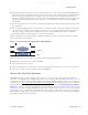
AP1000 Beta Test Install the AP300 Figure 6: AP320, AP311 or AP302 Antennas 1-6 in Ceiling and Wall Mount Configuration 6 (vertical) 5 (horizontal) 3 (vertical) 1 (horizontal) A 2 2 L A N R F 1 R F 2 A A 2 2 (horizontal) 4 (horizontal) The following antenna connections are used during operation of the AP320, AP311, and AP302. Note that PSM3x APs will only have four antennas, rather than the typical six.
AP1000 Beta Test Install the AP300 Table 2: AP310 With One Radios and Corresponding Antennas Model AP310 Radio 1 (Ant1, Ant2, Ant3) a/b/g/n with 3 dual band omni-directional antennas The AP310 has six external antenna ports labeled 1 - 6. However, AP310 uses only three of those antennas and the unused antenna connectors are blocked. Figure 7 illustrates the recommended antenna configuration for the AP310.
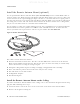
AP1000 Beta Test Install the AP300 Install the Remote Antenna Mount (optional) Use the optional Meru Remote Antenna Mount (ACC-ANT-MIMO-MNT) for one or both AP300 radios to remotely connect the AP300 antennas. The Remote Antenna Mount allows you to relocate either your current antennas or the optional high-gain dipole antennas to a location with clearer signal paths to the other wireless devices in your network. The Remote Antenna Mount can be installed either below the ceiling tile or on the wall.
AP1000 Beta Test Install the AP300 3. Using the template, drill holes in the ceiling tile. 4. Replace the ceiling tile. 5. Remove a ceiling tile adjacent to the newly drilled tile for access purposes. 6. Feed the Antenna Mount cable through the larger hole in the ceiling tile until the Antenna Mount is flush with the ceiling. The screw should now be visible above the ceiling tile (through the second hole). 7. Place the triangular plate above the ceiling tile with the screw aligned through the plate. 8.
AP1000 Beta Test Install the AP300 Install External ACC-ANT-MIMO-MNT Antenna with Three Connectors (optional) You can optionally use an external antenna setup with your AP300 if the controller and APs are running System Director 3.6.1MR4 and later. Meru supports this antenna for use on one radio using 802.11n MIMO. An AP300 with one radio, for example AP310, needs one antenna. An AP300 with two radios, for example AP320, needs two antennas. Radio One antenna cables connect to ports A1, A2, and A3.
AP1000 Beta Test Install the AP300 Using This Cable Type with 5 GHz Calculate This Loss per Foot LMR200 0.24 dB LMR240 0.19 dB LMR400 0.100 dB LMR600 0.066 dB © 2010 Meru Networks, Inc.
AP1000 Beta Test Install the AP300 Install Remote ACC-ANT-6ABGN-24 Antenna with Six Connectors (optional) You can optionally use an external antenna setup with your AP300 if the controller and APs are running System Director 3.6.1MR4 and later. Meru supports this antenna for use on AP300s with two radios, for example AP320. This antenna has six connectors to connect to both radios to a dual-radio AP300 and it supports 802.11n MIMO operation.
AP1000 Beta Test Install the AP300 Using This Cable Type with 2.4 GHz Calculate This Loss per Foot RG174 0.60 dB RG316 0.48 dB LMR100 0.39 dB LMR200 0.17 dB LMR240 0.13 dB LMR400 0.066 dB LMR600 0.043 dB Using This Cable Type with 5 GHz Calculate This Loss per Foot RG174 1.02 RG316 0.76 LMR100 0.59 dB LMR200 0.24 dB LMR240 0.19 dB LMR400 0.100 dB LMR600 0.
AP1000 Beta Test Install the AP300 AP Has One BG or A Radio, One Antenna A6 A5 Meru A4 A3 A2 A1 (BG or A radio antenna) AP Has Two Radios (BG and A), One Antenna For Each A6 A5 (BG radio antenna) Meru A4 A3 A2 A1 (A radio antenna) AP Has One Radio, Two Antennas A6 A5 Meru (BG or A radio antenna) A4 A3 A2 A1 (BG or A radio antenna) AP Has Two Radios, Four Antennas A6 A5 (BG radio antenna) Meru (BG radio antenna) A4 A3 A2 A1 (A radio antenna) (A radio antenna) 26 Meru Acc
AP1000 Beta Test Install the AP300 Install the Access Point AP300 ships with a detachable mounting bracket. The AP300 is designed to be compatible with brackets supplied by Meru and by other vendors as follows. The AP300 mounts directly on the AP150 mounting bracket. If you are replacing AP200s/AP300s, the AP300 bracket can be mounted on the old AP200s/AP300s bracket with included shoulder screws; you don’t need to remove the old brackets.
AP1000 Beta Test Install the AP300 Caution! Be sure to connect the Ethernet cable to the Ethernet port; the cable can mistakenly be plugged into the Console port. If you do this, the AP won’t power up. 7. If you are not using a PoE device, connect an external power supply to the power connector and plug it into the wall.
AP1000 Beta Test Install the AP300 8. Align the AP300 mounting posts over the circular portion of the keyhole mounts, push the AP in and slide the AP down until it engages with the locking detents (see Figure 9). You should hear it snap in place. 9. For each antenna, loosen the knurled ring at the base of the antenna, orient the antenna and then retighten the ring. 10. Connect one end of the PoE 100BaseT Ethernet cable to the 100/1000 Ethernet connector.
AP1000 Beta Test Install the AP300 Mount AP300 Above a Suspended Ceiling (Plenum) Use the optional T-bar box hanger mounting kit (see Mounting Brackets for the part number) to mount AP300 above suspended ceiling T-rails (see Figure 10 and Figure 11). The installation attaches the Tbar box hanger to the ceiling rails and then the AP300 attaches to the T-bar box hanger. We recommend that you mount the AP300 no more than half way up the supports as shown in both Figure 10 and Figure 11.
AP1000 Beta Test Install the AP300 00232 Figure 11: AP300 Mounted Above a Suspended Ceiling Face Up The AP300 with the metal enclosure exposed meets the requirements for fire resistance and low smoke-generating characteristics required by Section 300-22(C) of the National Electrical Code (NEC) for installation in a building’s environmental air space. You may need to modify thicker tiles to support this installation.
AP1000 Beta Test Install the AP300 To mount an AP300 above the ceiling with the optional T-bar kit, follow these steps: 1. Determine the location on the ceiling rails where the AP will be mounted and remove the ceiling tile. 2. Unpack the T-bar hanger kit and unfold the legs of the T-bar hanger. 3. Locate the bracket mounting clip holes on the mounting bracket (see Figure 10). One hole attaches the bracket perpendicular to the box hanger; the other mounts the bracket parallel to the box hanger. 4.
AP1000 Beta Test Install the AP300 6. Hold the AP300 next to the mounting bracket to estimate the height of the T-bar box hanger. You need to provide enough clearance for the external antennas that point down, while mounting the T-bar on the lower half of the support rails for stability. 7. Adjust the height of the box hanger using the height adjusting screws (see Figure 9). 8. Clip the box hanger T-rail clips to the ceiling rails, making sure they are securely attached. 9.
AP1000 Beta Test Check AP300 LED Activity 00230 Figure 14: Hoffman Bracket ACC-AP300-BHE 6. Using a Phillips screw driver, attach the bracket using the two supplied 6-32 3/16 SEMS screws. 7. Flip the assembly over and mount into the Hoffman enclosure, attach the Ethernet cable to the AP300 rotating the assembly to place the Ethernet cable within the enclosure. 8. Using a Phillips screw driver, tighten the four bracket screws to the enclosure. 9. Adjust the antennas as needed.
AP1000 Beta Test Check AP300 LED Activity AP300/AP300i LED Descriptions LED Power Function Troubleshooting off—no power green—presence of power off—no power green—booting stage 1 blinking green and off—booting stage 2 blinking green and white—discovering the controller Status blinking green and blue—downloading a configuration from the controller blinking blue and off—AP is online and enabled, working state If the status LED is blinking red and yellow, there is an alarm on the AP.
AP1000 Beta Test Where to Go From Here Change LED Appearance If you want to change the appearance of the LEDS, follow these steps: 1. From the controller, click Configuration > Devices > AP, and then select the AP. 2. Select one of these settings for the LED Mode setting: — Normal: LEDs are as described below — Node ID: Not supported in release 4.1 — Blink: Sets all LEDs flashing; this is useful to locate an AP — Dark: Turns off all LEDs 3. Click OK.