
User's Manual
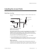
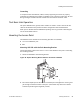
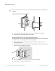
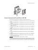
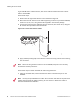

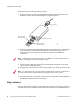
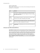
Table Of Contents
- About This Guide
- Meru Access Points and Radio Switch
- Installing the AP300
- Installing the AP200
- Installing the OAP180
- Installing the AP150
- Installing the RS4000
- Specifications
- AP Accessories
- Mounting Bracket Stencils
- Cautions and Warnings
- Regulatory Information

54 Meru Access Point and Radio Switch Installation Guide © 2008 Meru Networks, Inc.
Installing the Access Points
Follow these steps to connect the power injector:
1. Connect the other end of the provided Ethernet cable (already connected to the
OAP180) to the RJ-45 port labeled Output on the power injector.
2. Connect a straight-through unshielded twisted-pair (UTP) cable (not included) from a
local LAN switch to the RJ-45 port labeled Input on the power injector. See the
illustration above. Use Category 5e or better UTP cable for 10/100BASE-TX
connections.
3. Insert the power cable plug directly into the standard AC receptacle on the power
injector. See the illustration above.
4. Plug the other end of the power cable into a grounded, 3-pin socket, AC power source.
5. Check the LED on top of the power injector to be sure that power is being supplied to
the OAP180 through the Ethernet connection.
Align Antenna
After the OAP180 unit is mounted, connected, and the radios are operating, the anten-
nas must be accurately aligned to ensure optimum performance of the OAP180 links. In
AC power
Power LED indicator
Ethernet cable
from LAN switch
Ethernet cable to
wireless bridge
00206
Note:
The RJ-45 port on the power injector is an MDI port. If connecting directly to a
computer for testing the link, use a crossover cable.
Note:
For International use, you may need to change the AC line cord. You must use a
line cord set that has been approved for the receptacle type in your country.