
User's Manual
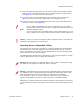
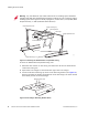
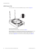
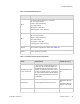
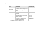
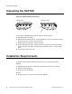
Table Of Contents
- About This Guide
- Meru Access Points and Radio Switch
- Installing the AP300
- Installing the AP200
- Installing the OAP180
- Installing the AP150
- Installing the RS4000
- Specifications
- AP Accessories
- Mounting Bracket Stencils
- Cautions and Warnings
- Regulatory Information

46 Meru Access Point and Radio Switch Installation Guide © 2008 Meru Networks, Inc.
Unpacking the OAP180
Unpacking the OAP180
Figure 26: OAP180 Outdoor Access Point
Confirm that the OAP180 shipping boxes contain the following items:
z OAP180 Outdoor Access Point
z Wall/Pole Mount Hardware Kit for mounting OAP180 to a 1.5” to 2” diameter steel pole
or tube or as part of a radio or tower structure
z N-Type Female connectors for external antennas
z Outdoor CAT5 Ethernet cable—100 feet. Be sure to include this (maximum) 100 foot
cable in link path calculation; the PoE does not resend the traffic, it only provides
power.
z Power injector with power cord
Installation Requirements
In addition to the hardware supplied by Meru Networks, you need the following:
Required
z Standard Ethernet cable to connect the power injector to a switch or controller
z Antennas (sold separately)
z Ground wire for the OAP180
Optional
z RF coaxial cable to connect the antenna to the OAP180
00195
Top panel view Bottom panel view
Console
Port
Console
Port Cover
Attachment
Ethernet/PoE
Connector
2.4G 2.4G5G 5G
N-Type External
Antenna Connector
(5 GHz)
N-Type External
Antenna Connector
(2.4 GHz)
Console PoE
Water-Tight
Test Point