
User's Manual
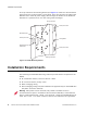
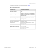
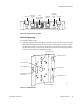
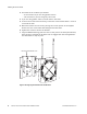
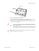
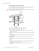
Table Of Contents
- About This Guide
- Meru Access Points and Radio Switch
- Installing the AP300
- Installing the AP200
- Installing the OAP180
- Installing the AP150
- Installing the RS4000
- Specifications
- AP Accessories
- Mounting Bracket Stencils
- Cautions and Warnings
- Regulatory Information

Installing the Access Points
© 2008 Meru Networks, Inc. Installing the AP200 33
Figure 16: AP200 Connector Panel
Vertical Mounting
To vertically mount an AP:
1. Using the bracket holes as a template, mark the location on the wall for the two
AP bracket mounting screws. They are placed 4 ½ inches apart, center-to-center,
one above the other. If you are not using plastic wall anchors, you must center
the mounting screws on a wall stud. If you do not center the mounting screws on
a wall stud, you must use plastic wall anchors.
Figure 17: AP200 Bracket
CONSOLE
ANT 1
ANT 2
3.3 VDC
ETHERNET
0
0108
100/1000
Ethernet
(Reserved)
Console
port
Antenna 1 Antenna 2
Power
inlet
Reset
(Push to restore
default settings)
(Currently
unsupported)
Access point mount
Ceiling mount hole
Ceiling mount hole
A
ccess point mount
Access point mount
Locking detent
W
all cable access
S
uspended ceiling
c
able access
00100