
User's Manual
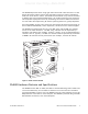
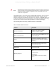
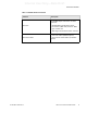
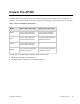
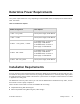
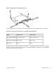
Table Of Contents
- About This Guide
- Meru Access Points and Radio Switch
- Installing the AP300
- Installing the AP200
- Installing the OAP180
- Installing the AP150
- Installing the RS4000
- Specifications
- AP Accessories
- Mounting Bracket Stencils
- Cautions and Warnings
- Regulatory Information

© 2008 Meru Networks, Inc. Installing the AP300 13
Determine Power Requirements
Your power requirements will vary, depending on which AP300 radios are deployed and what mode is
used. See below.
Table 3: AP300 Power Options
Installation Requirements
An array of holes on the mounting bracket allows the AP300 to be mounted on the wall and over junc-
tion boxes or molly bolts. There are holes for passing the PoE Ethernet or external power supply cable
through the bracket if the bracket is mounted on a junction box. A template of this bracket is included
in Appendix E of this guide.
The AP300 has a security cable slot so you can lock the AP300 with a standard security cable, such as
those used to secure laptop computers.
These two kits can be used to mount the AP300 from the ceiling:
z Suspended Ceiling Rail Mounting Kit
z Above Suspended Ceiling Mounting Kit (T-Bar Hanger)
AP300 Configuration Power Options
1 radio – a/b/g mode External power supply or PoE 802.3af
1 radio – n-mode External power supply or PoE 802.3af
2 radios – 1 a/b/g mode, 1 n mode
For 2x2 MIMO mode, use either a
power supply or PoE 802.3af.
For 3x3 MIMO mode, use either a
power supply or a PoE 802.3at.
2 radios – both n mode
For 2x2 MIMO mode, use either a
power supply or PoE 802.3af.
For 3x3 MIMO mode, use either a
power supply or a PoE 802.3at.
2 radios – both a/b/g mode External power supply or PoE 802.3af