
User's Manual
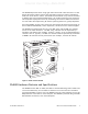
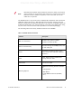
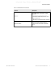
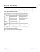
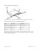
Table Of Contents
- About This Guide
- Meru Access Points and Radio Switch
- Installing the AP300
- Installing the AP200
- Installing the OAP180
- Installing the AP150
- Installing the RS4000
- Specifications
- AP Accessories
- Mounting Bracket Stencils
- Cautions and Warnings
- Regulatory Information

© 2008 Meru Networks, Inc. Meru Access Points and Radio Switch 8
Internal Use Only—Beta Draft
.
The RS4000 works in conjunction with a wideband RF combination omni directional
(WRC/OD) indoor antenna or a 180-degree directional indoor antenna. Only one
antenna is needed for simultaneous operation of all radios of an RS4000 in both the
2.4GHz and 5GHz bands. The antenna must be connected to the Radio Switch using
any one of the low-loss antenna cables provided in the antenna packaging.
The following table lists the key hardware features of the RS4000.
Note:
PoE must be provided on the first Ethernet connector (ETH1); the antenna
cannot operate correctly without that power source. Power to the second
Ethernet connector (ETH2 ) is optional; if not connected, two of the
radios will not operate.
Table 1: RS4000 Hardware Features
Feature Description
802.11 Connectivity
Two 802.11b/g radios (2.4GHz)
Two 802.11a radios (5 GHz)
Ethernet Connectivity
Two auto-sensing 10/100 Mbps ports, one
for each radio pair
Power
Provided by two 802.3af POE connec-
tions, one for each radio pair (15W per
connector)
LEDs
Power, Radio Activity, and Ethernet
Activity LEDs per radio
Dimensions 9.5" x 8.5" x 3.875"
Mounting Options
RS4000 has mounting brackets available
for:
z Ceiling Mount
z Wall Mount
z Inside NEMA Enclosures (Hoffman,
etc.)