
User's Manual
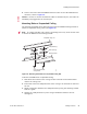


Table Of Contents
- About This Guide
- Meru Access Points and Radio Switch
- Installing the RS4000
- Installing the AP200
- Installing the AP150
- Specifications
- Regulatory Information
- Channels
- Mounting Bracket Stencils

Checking LED Activity
© 2007 Meru Networks, Inc. Installing the AP200 45
Table 6: AP200 LED Descriptions
Table 7: AP200 Controller Status Information
LED Function
RF 2
The status LED for Radio 2 is a follows:
off—no radio present
yellow—radio initializing
red—radio failure
solid green—radio OK
blinking green—radio activity
RF 1
The status LED for Radio 1 is a follows:
off—no radio present
yellow—radio initializing
red—radio failure
solid green—radio OK
blinking green—radio activity
Status AP-Controller operational status (see Tabl e 7)
Power green—presence of power
State Interpretation AP200 LED Cycle
Attempting to dis-
cover Controller
In the process of discovering the con-
troller. The AP is connected but not
associated with the controller. If the
AP does not associate with the control-
ler after a period of time, verify that
the connection between the AP and the
switch or the switch and the controller
is unbroken.
Green/Red/Blue/R
ed
Connected Normal operation without security.
Blue/Blue/Blue/R
ed
Blue/Blue/Blue/R
ed, for 2 seconds.
Authenticated Normal operation with security. Blue blink
a