
User's Manual


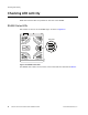
Table Of Contents
- About This Guide
- Meru Access Points and Radio Switch
- Installing the RS4000
- Installing the AP200
- Installing the AP150
- Specifications
- Regulatory Information
- Channels
- Mounting Bracket Stencils

22 Meru Access Point and Radio Switch Installation Guide © 2007 Meru Networks, Inc.
Installing the RS4000
5. Pass the long end clip through the large center hole to the underside of the the
mounting bracket clip and then attach the bracket to the clip using the supplied
screw (see Figure 13 for orientation).
6. Hold the RS4000 next to the mounting bracket to estimate the height of the T-bar
box hanger to provide enough clearance between the RS4000 and the ceiling.
7. Adjust the height of the box hanger using the height adjusting screws (see
Figure 13).
8. Clip the box hanger T-rail clips to the ceiling rails, making sure they are securely
attached.
9. Connect a drop wire to a building structural element and through the hole
provided in the bracket mounting clip. The U.S. National Electrical Safety Code
requires this additional support.
10. Align the RS4000 to the bracket and tighten the four knurled thumbscrews until
secure. If necessary, apply extra tightening with pliers.
11. On the RS4000, attach the two antenna cables to the SMA antenna connectors
labeled
ANT1 and ANT2 on the top panel of the RS4000 (see Figure 8) by turning
the cable ends clockwise until tight.
Figure 14: RS4000 with Antenna Attached
12. Attach at least one Ethernet cable to the Ethernet port labeled
ETH1 and
optionally to
ETH2 on the top panel of the RS4000. If just ETH1 is connected, only
two of the four radios will be active.
13. Attach the antenna cables to the antenna, as described in “Placing and
Positioning the Antenna.” The antenna can also be mounted within the plenum
space if need be.
14. Connect the Ethernet cables to the PoE device.
15. Apply power to the PoE component and network switch to power up the RS4000.
K
00182
ANT1 ANT2
ETH1
ETH2
ANT1
ANT2
(Meru logo is upside down)