
Installation Guide


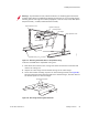


Table Of Contents
- About This Guide
- Meru Access Points and Radio Switch
- Installing the RS4000
- Installing the AP200
- Installing the AP150
- Specifications
- Regulatory Information
- Channels
- Mounting Bracket Stencils
42 Meru Access Point and Radio Switch Installation Guide © 2007 Meru Networks, Inc.
Installing the Access Points
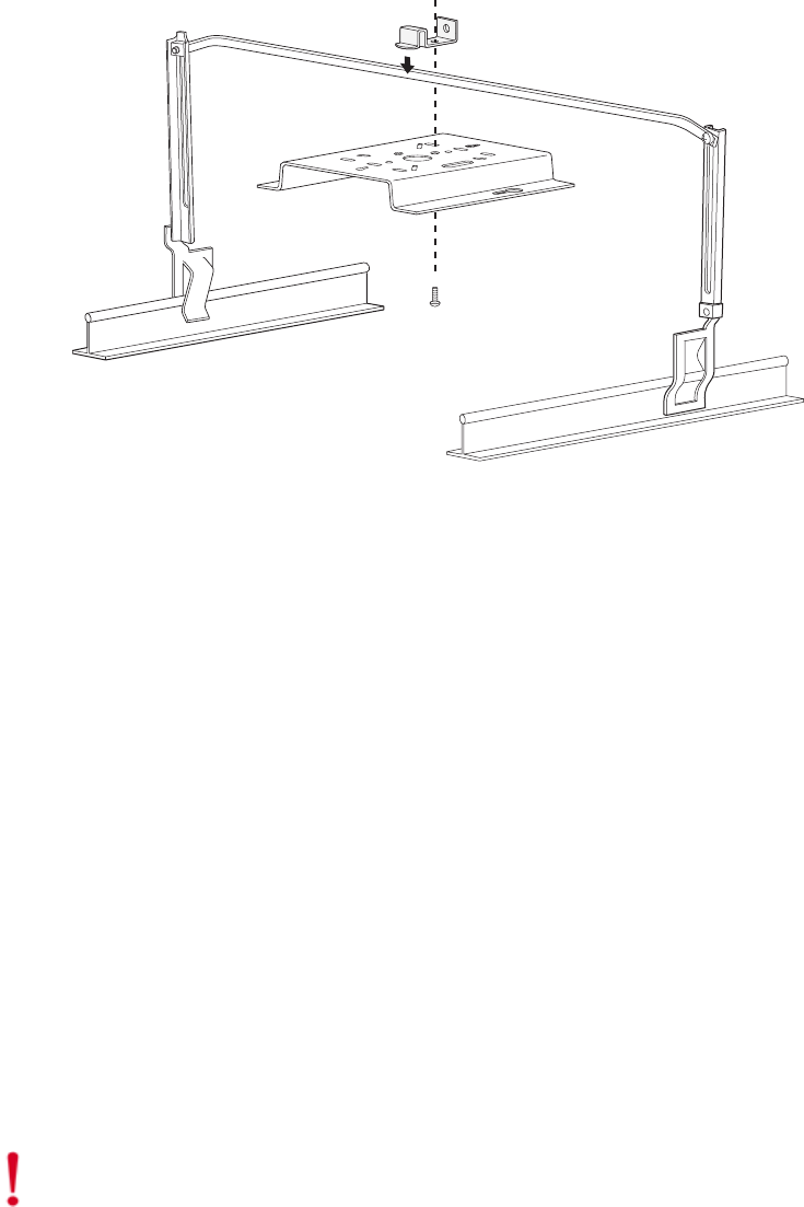
4. Attach the U-joint of the clip to the T-bar and snap in place (see Figure 29).
.
Figure 29: Attaching the Mounting Bracket to the Box Hanger
5. Pass the long end clip through the large center hole to the underside of the the
mounting bracket clip and then attach the bracket to the clip using the supplied
screw (see Figure 29 for orientation).
6. Hold the AP200 next to the mounting bracket to estimate the height of the T-bar
box hanger to provide enough clearance for the external antennas, which should
be pointing down.
7. Adjust the height of the box hanger using the height adjusting screws (see
Figure 26).
8. Clip the box hanger T-rail clips to the ceiling rails, making sure they are securely
attached.
9. Connect a drop wire to a building structural element and through the hole
provided in the bracket mounting clip. The U.S. National Electrical Safety Code
requires this additional support.
10. Connect the posts of the AP200 to the three keyholes of the mounting bracket and
slide into the keyhole (see Figure 25), ensuring the locking detent is engaged. You
will hear a click.
11. For each antenna, loosen the knurled ring at the base of the antenna (see
Figure 21), point the antenna down, then retighten the ring.
12. Connect one end of the PoE 100BaseT Ethernet cable to the 100/1000 Ethernet
connector, shown in Figure 22.
00104
Caution!
Be sure to connect the Ethernet cable to the Ethernet port; the cable can
mistakenly be plugged into the Console port.