
Operating instructions


22
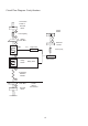
AC input from
Aux Transformer
D20 L ED
ON
when power is on
OFF
when Microwave is
operated.
Magentron
Overheat sensor
Inputs
Cavity
Temperature
Sensor
Input
Connector To
Logic PCB
D19 Heater ON
U1 Ambient air
temperature
se n so r
Piezo sounder
output
F u se
Not Us e d
Di sp l a y
F u se
D16 Magnetron
soft sta rt
D15 Magnetron
active
Display
Connecter
Relay PCB 15 way
Connecter
Motor speed
controller
Membrane panel
connector
MenuKey
Socke t
Connector
Door
Switch IP
Program
memory storage.
Chip m ay be
exchanged
with New PCB i f
PCB repl aced.
D7 Power LED
Indicates Logic PCB
is powered
See Troubl esho oting
Guide
Door switch
Indicator
ON w hen door
closed
Temp Calibration
Remote data
point
Spare input
(not used)
Fibre Optic
Detector 1 to LHS
Fibre Optic
Detector 2 to RHS
Magnetron 2
Magnetron 1
Fibre Optic Magnetron
Detection
Solid State Relay
Heater regulation
circuit
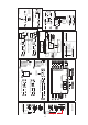
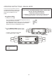
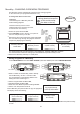
PCB Connections & LED Indicators
Logic board:
D6 Is in series with signal to the Motor Speed Controller output.
Bright when fan speed is 100%, dimmed when Fan speed is
10% with the oven door open.
D7 Low voltage power on
D8 Flashes typically 1x per second to indicate that internal memory
is being accessed.
D11 ON when door is closed,
OFF when door is opened
D10 Illuminates when the main micro processor is accessing the
MenuKey socket.
Relay PCB:
D15 Magnetron active
D16 Magnetron soft start
D19 Heating elements heating up
D20 ON when Low Voltage power is on, is OFF when microwave is
operated.
D8
D10
D6
D11
D7