
Operating instructions


14
31
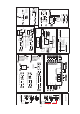
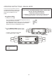
Power
Switch
36
51
41
Fuse6[10A]
Terminal
Block
Mains
Filter Mf3
30
Power
Switch
37
56
Terminal
Block
Mains
Filter MF3
M M
M
M
25 21 29
47
48
2823 2224 20 27 26
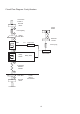
Hot Air
Motor
Cooling
Fan
Cooling
Fan
Black
Brown
Blue
Blue 0V
Yellow
Red 10V
Hot Air Motor
Controller
Low Voltage
Power to
Logic PCB
Logic
PCB
Low Voltage
Transformer
Fuse 9
1 Amp
Fuse 1
1.6 Amp
Jp1
Cavity
Overheat
Sensor
[Reset
Possible]
Stirrer
Motor
LHS
Stirrer
Motor
RHS
Relay PCB
Circuit Flow Diagram: Motors, Fans and Low Voltage Circuit