
Operating instructions


13
Standard Tests
Before carrying out diagnostics on the oven.
1. Check the Power Supply and conrm the Voltage is within +/- 10%
of the nominal supply rating.
2. Check that the Oven is installed properly
3. The Filter is installed correctly postioned in the Filter Base (
Incorrect tting will cut the power to the oven
4. The oven is plugged in to the correct type of power supply.
5. Error messages in the display
Service diagnosis measurement is recommended as follows:
Please notice what is happening when the oven is switched on:
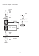
Using the Circuit Flow diagram on page 14 as a
Guide.
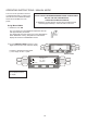
Check the input power supply at the Terminal Block is typically
between 220-230 Volt (L1 and L2 versus neutral)
If Fuse 4 blows check that the Door operated Micro-switches at each
side of the oven are adjusted correctly
The Low Voltage should be present at the logic board and the relay
board which control the operation of the oven.
LED’s will come on if Low Voltage is present on the Logic board and
the Relay board.
The on/off switch also initiates the Microwave Stirrer Motors left and
right to run.
The on/off switch initiates the Cooling Fan to run
The on/off switch initiates the Convection Hot Air Motor to run (Only if
the Low Voltage is present)
The display lights up with informational text.
If some of the above does not occur use the Circuit Flow diagram for
ease of fault nding. (page …)
If this all works the oven can be tested on the 3 Oven heating/cooking
aspects.
1. Hot air motor,
2. The heating elements
3. Microwave
ensure the following:
During PREHEAT start up (from cold) the Heating elements current
draw can be measured on wire 40 at Fuse 2 (20 Amp) typically 14.5
– 15.1 Amp
There are 5 elements of each 650 W, So a failing element can drop
the current with approx. 2.8 Amp per element
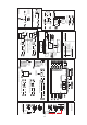
Circuit Flow Diagram (Page 15) provides you with the current
diagram and easy fault nding information.
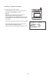
The Hot Air Motor Controller can be checked by listening to the
decrease in hot air motor speed if you open the door. The Hot air
motor runs at 50% of the speed when the door is closed and on 20%
if the door is opened. By measuring the DC voltage on connector JP
15 Logic Board wires Blue and Yellow you can double check. 20% is
typically 1.9 – 2.1 VDC and 50% is typically 4.9 – 5.1 VDC
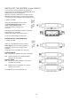
To measure the Magnetron current draw you will need to set the
oven to Manual Mode (set the pre-heat to zero) and operate the
magnetrons (WARNING do not forget to put a load in the cavity, not
with an empty oven) You may notice the LED’s on the Logic PCB for
the Magnetron detect from the Fibre optics, also notice the LED’s
D15 and D20 on the Relay Board while measuring the current on wire
44 at Fuse 8 and wire 46 at Fuse 7.
Typical current draw is between 5.6 – 6.5 Amps (Using Circuit Flow
Diagram on page 16 will help to follow the circuit)
Do not forget to carry out a component measurement test in case you
nd errors in the magnetron environment. (WARNING Disconnect
from the power supply and discharge the capacitor before touching
any component)
Download the menu back from your MenuKey to the oven or set the
PREHEAT temperature back to the original setting as it should be
and save the settings.
Carry out an emission measurement test.