
Service manual

Page 15 Mealstream 401Ovens 32Z3311 Issue 8
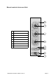
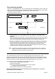
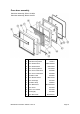
1. Primary Interlock [ 55 , Top Left-Hand ] and Low voltage [ 56 , Top Right-Hand ]
Switches
Operate simultaneously. Either will cut off the microwave emissions from the oven when the
door is opened: the Primary switch by breaking the mains supply circuit to the transformers,
and the Low-Voltage switch by breaking the relay circuit on the Power / Relay PCB.
2. Monitor [ 58 , Bottom Outer ] and Secondary Interlock [ 57 , Bottom Inner ] Switches.
Operate simultaneously. The Monitor switch will produce a short circuit across the mains
supply if the Primary interlock switch is faulty, thus blowing the microwave fuse and
rendering the oven inoperative. The Secondary interlock switch will cut off the microwave
emission if all three of the other switches have failed.
Note: If operation of the Monitor switch has caused the Microwave Fuse to blow, the
Primary and Monitor microswitches must be changed, as they may have been
damaged by the high short-circuit currents involved.
Door Interlock Arrangement
Power In Power Out
L
N
55
56
57
58
Error Light Operation
The “Air Filter Blocked” light and “Service” light are triggered by the internal circuitry. If the
magnetron overheats, the error code “E:7” is displayed on the front panel, and both the “Air Filter
Blocked” and the “Service” indicators will light. Once the magnetron has cooled sufficiently to allow
the oven to restart, the “Service” light will remain illuminated until the oven is turned off.
This fault may have been triggered by one of the following causes:
- Air inlet on rear of machine being obstructed.
- High air inlet temperature.
- Slow running cooling fan, jammed turntable or broken gearbox
(cooling fan also drives turntable).
- Faulty magnetron overheat ‘stat or associated wiring.
Note that the customer may not have noticed that the oven displayed “E:7”, and so the
reported fault may be misleading.
Door interlock operation
The door on the Mealstream 401 oven is monitored by four microswitches. Three of these are
used in the conventional “Primary, Secondary and Monitor” switch arrangement shown below,
while the fourth is a low-voltage switch linked directly to the control circuitry.
The switches operate as follows:
Top RH
Bottom Inner
Bottom Outer
Top LH