
User Manual
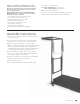

Wall Unit Owner’s Manual
2
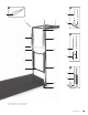
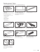
1 Horizontal Frame Assembly
2
3
⁄8" Hex Bolts (pre-set)
3 Roll-Down Springs (2) (black)
4 Three-Way Joint
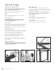
5 Safety Chain [fig. A]
6 Roll-Down Bar
7
1
⁄2" Hex Bolts (pre-set)
8 Leg Springs (2) (white) [fig. C]
9 Push-Thru Bar
10 Padded Long Spine Straps [fig. C]
11 Base Plate
12 Vertical Frame
13 Arm Springs (2) (yellow) [fig. B]
14 Foam-Grip Handles [fig. B]
15 Push-Thru Springs (2) (blue) [fig. D]
16 Locking Spring Clip [fig. D]
17 Push-Thru Spring Cover [fig. D]
18 Eye Hooks – Upper
19 Eye Hooks – Lower
Part Identification for the Wall Unit
Hardware Required
(NOT INCLUDED)
Specific bolts and/or screws used in the installation of the frame and
base plate would depend on the type of surface it is being affixed to,
although it is always recommended that you try to attach to a wall stud.
Your local hardware store or contractor would be able to assist you
in selecting the appropriate hardware for your specific needs.
Affixing to drywall:
Butterfly toggle or slotted hex head wall anchors
Affixing to brick wall:
Masonry fasteners
Affixing to ceramic tile floor:
Masonry fasteners
Affixing to wood floor/carpeting:
Wood screws
REQUIRED TOOLS
INCLUDED:
universal assembly tool
NOT INCLUDED:
builder’s level
drill