
Operating instructions


30 V DC
+ -
0 1 2 2 3 4 5 6 7
UP
DOWN
PROG
LEARN
(YELLOW)
INDICATOR
LED
1
2
3
4
5
6
7
8
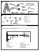
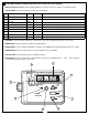
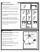
1. External Accessory Power: 30 Vdc 50 mA available for universal receiver (not active in Low standby mode).
2. Terminal Block: used for external accessories (see chart below).
3. UP Button: used for initial programming, to drive the door UP, and for displaying Diagnostic Code - Digit 1.
4. PROG Button: used to program door limits, and other features.
5. DOWN Button: used for initial programming, to drive the door DOWN, and for displaying Diagnostic Code - Digit 2.
6. LEARN Button: used to program remote controls and learn the forces manually.
7. Indicator LED: used to indicate various programming modes.
8. Green Button: used to activate the door when remote controls are not available. Open - Stop - Close via finger
access through the hole in the access cover.
No Function Colour Polarity Comment
0
E-Serial port Green +ve
Serial Communication Input
1
Push button Red +ve
Dry Contact input for push button wired wall controls
2 Ground White -ve
Common terminal for push button
2
Ground White -ve
Common terminal for IR Beams
3
IR Sensor Gray +ve Merlin IR Beam Input: (pulsing type only)
4
Door-in-door Green +ve
For Door in Door dry contact sensor: (4&5 are normally linked)
5
Door-in-door Green -ve Common terminal for Door in Door sensor
6
Flasher Black +ve Flashing light output: (24 Vdc 150 mA) while door is in motion
7
Flasher White -ve Flashing light output: negative terminal
CONTROL PANEL (located under the cover at the rear of the opener)
5
7