
Operating instructions


1
2
4
5
6
7
8
9
10
11
3
12
14
I
MPORTANTSAFETYinformation
TALLATIONBEFOREREADINGTHOROUGHLY
N2966N2966N2966N2966
13
OwnersCopy:SAVETHESEINSTRUCTIONSforfuturereference
MT100EVO
S
ectional and Tilt Garage Door Opener
Installation and Operating Instructions
Thismanual contains IMPORTANT SAFETY information
D
ONOT PROCEED WITH THE INSTALLATIONBEFORE READING THOROUGHLY
N2966N2966N2966N2966
gomerlin.com.au
gomerlin.co.nz
1
14A3361
ForService Call
InstallationDate
1
32A2900
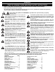
RISKOF ENTRAPMENT
RepeatSafety Reverse Test monthly Door
mustreverse on contact with a 40mm obstacle
p
lacedon the floor Makenecessary adjustments
AUTOMATICDRIVE:
Keepaway from the area of the door since it may
o
perateunexpectedly
EMERGENCYRELEASE:
Torelease pulldown firmly on the red handle
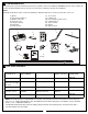
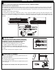
CARTON INVENTORY
(
1) Opener
(2) Hand held transmitter (2)
(3) Wireless wall control
(4) Curved door arm
(5) Hanging bracket (2)
(6) Rail bracket
(7) Header bracket
(
8) Door bracket
(9) Hardware bag
(10) Rail assembly (separate carton)
(11) C-Rail bracket (2)
(12) Tilt door bracket
(13) Manual
(14) Warning Labels
Y
our garage door opener and rail are packed in two seperate cartons. The tiltmaster MT100EVO opener carton contains the
opener, its fitting hardware and accessories. The rail carton contains the rail and some hardware.
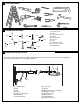
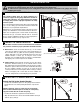
Rails:
Different length rails (2.2 m & 2.4 m) are available for different height doors, ensure you have the correct one.
2
RAIL SIZES AVAILABLE
3
DOOR HEIGHT:
Sectional Doors
BELT & RAIL
PART NUMBER:
RAIL LENGTH: CEILING FIXING
POINTS: (standard)
ALTERNATE
FIXING POINT:
Up to 2.2 m
8022 CR5 3000 mm single piece 2840 mm
2950 mm
Up to 2.2 m
(not for use on J-type
tilt doors)
8322 CR5 3000 mm segmented 2840 mm
2950 mm
Up to 2.4 m 8024 CR5 3200 mm single piece 3040 mm
3150 mm
From 2.4 - 3.4 m 840 CR5 1000 mm extension 4040 mm
4150 mm
2.3 m TILT Door 820 CR5 2000 mm single piece 1840 mm
1950 mm
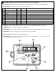
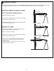
NOTE: The Ceiling Fixing Point (Standard) is the position of the hanging bracket measured back from the lintel (see
item 1 to 7 of “completed installation”). Also allow 400 mm back from the fixing point for installation of the powerhead
(item 7 to 9 of “completed installation”).
The Alternate Fixing Point will position the hanging bracket between the C-Rail brackets, and may line up with a
structural support more favourably.
3