www.merlingo.
START BY READING THESE IMPORTANT SAFETY INSTRUCTIONS WARNING • Failure to comply with the following instructions may result in serious personal injury or property damage. • Read and follow all instructions carefully. • The garage door opener is designed and tested to offer safe service provided it is installed and operated in strict accordance with the instructions in this manual. These safety alert symbols mean WARNING : A possible risk to personal safety or property damage exists.
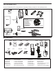
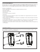
CARTON INVENTORY Your door opener is packaged in one carton which contains the opener and the parts illustrated below. Note that accessories will depend on the model purchased. If anything is missing, carefully check the packing material. 2 x C945 3ch rolling code transmitters Extension plate Angle bracket Mounting brackets Opener Manual Manual release handle x x x x x x x x x x x 1 1 1 3 5 2 3 3 6 12 6 WARNING NOTI CE Base plate Sprocket incl. Half Brush Bush Retainer incl.
PREPARING YOUR DOOR BEFORE YOU BEGIN: To prevent possible SERIOUS INJURY or DEATH: • ALWAYS call a trained door systems technician if door binds, sticks or is out of balance. An unbalanced door may not reverse when required. • NEVER try to loosen, move or adjust door, door springs, cables, pulleys, brackets or their hardware, ALL of which are under EXTREME tension.
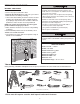
DOOR REQUIREMENTS Survey the area to see if any of the conditions below apply to your installation. Additional materials may be required. You may find it helpful to refer back to this page as you proceed with the installation of your opener. Depending on your requirements, there are several installation steps which may call for materials or hardware not included in the carton.
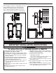
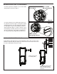
CHAIN ALIGNMENT CONSIDERATION Outboard (conventional) Inboard (no side room) Min. 20mm Min. 20mm Min. 20mm Min. 20mm Before installing, consider the relationship between the opener and door in terms of the chain connection. Clearances are indicated below to demonstrate the range of sprocket positions available. Choose your opener mounting location based on the drawing below. INSTALLATION IMPORTANT INSTALLATION INSTRUCTIONS WARNING To reduce the risk of SEVERE INJURY or DEATH: 1.
INSTALLATION STEP 1 MOUNTING THE UNIT When mounting the unit there are several installation combinations all dependent on clearance and accessibility. Always mount to the side of the unit at which the sprocket will be fitted. Note: the wall angle below is shown in a particular orientation. This may vary from door to door. DIRECT EXISTING ANGLE MOUNT The unit can be mounted directly to an existing angle where suitable.
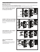
INSTALLATION STEP 2 Ensure all Drive spacer’s are corrected aligned and engaged with the recess in the base plate before attempting to operate the door. The door must be secure from movement before fitting the Chamberlain Easy-Fit Sprocket Kit. Suitable provisions must be made to ensure that no person/s may enter the area below the mounting location. Falling objects during installation may cause serious injury or death. EASY-FIT SPROCKET INSTALLATION 3/8” bolt 1.
INSTALLATION STEP 2 (CONTINUED) 4. Attach to sprocket using M8 x 16 Hex bolt and M8 spring washer as shown in figure 4. drive spacer M8 x 16 bolt M8 spring washer figure 4 figure 5 5. Loosely attach the two remaining drive spacers to the sprocket as shown in figure 5, using M8 x16 bolts and spring washers. The slots should correspond in the base plate to achieve desired distance between sprocket and base plate, see figure 5.
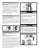
INSTALLATION STEP 3 ATTACH THE EMERGENCY RELEASE ROPE AND HANDLE Opener Emergency Release Cable • Thread one end of the rope through the hole in the top of the red handle so “NOTICE” reads right side up as shown. Secure with an overhand knot at least 25mm (1") from the end of the rope to prevent slipping. • Thread the other end of the rope through the loop in the emergency release cable. • Adjust rope length so the handle is no higher than 1.8m (6’) above the floor. Secure with an overhand knot.
INSTALLATION STEP 6 INSTALLING THE WIRELESS WALL BUTTON (CM128) (OPTIONAL ACCESSORY) Disconnect power to the opener whilst installing this accessory to prevent accidental activation. Locate minimum 1.5m above the floor. Control must be mounted out of the reach of children at a height of 1.5m with an unobstructed view of the door. • Ensure your MJ3800R opener is switched off whilst installing your wireless door control to prevent accidental activation. • Remove the cover from the CM128.
INSTALLATION STEP 8 INSTALL THE PROTECTOR SYSTEMTM Be sure power is not connected to the door opener BEFORE installing the safety reversing sensor. To prevent SERIOUS INJURY or DEATH from a closing door: • Correctly connect and align the safety reversing sensor. This required safety device MUST NOT be disabled. • Install the safety reversing sensor so beam is NO HIGHER than 100mm (4”) above the floor.
WIRING THE SAFETY REVERSING SENSORS • Run the wires from both safety reversing sensors to the opener. Use insulated staples to secure wire to wall and ceiling. • Strip 11mm (7/16") of insulation from each set of wires. Separate white and white/black wires sufficiently to connect to the opener quickconnect terminals: white to white and white/black to grey (shown right).
ADJUSTMENT STEP 1 PROGRAM THE TRAVEL LIMITS Travel limits regulate the points at which the door will stop when moving up or down. Follow the steps below to set the limits. Figure 1 Indicator Light Without a properly installed safety reversal system, persons (particularly children) could be SERIOUSLY INJURED or KILLED by a closing door. • NEVER learn forces or limits when door is binding or sticking. Repair door first.
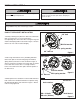
ADJUSTMENT STEP 2 SETTING THE FORCE The force setting button is located on the front panel. The force setting measures the amount of force required to open and close the door. 1. Locate the orange button on the unit (Figure 1). 2. Push the orange button twice to enter unit into Force Adjustment Mode (Figure 2). The LED (Indicator Light) will flash quickly. 3. Push the transmitter, wireless wall button or multifunction door control (Figure 3). The door will travel to the DOWN (close) position.
ADJUSTMENT STEP 3 TEST THE SAFETY REVERSAL SYSTEM Without a properly installed safety reversal system, persons (particularly children) could be SERIOUSLY INJURED or KILLED by a closing the door. • Safety reversal system MUST be tested every month. • If one control (force or travel limits) is adjusted, the other control may also need adjustment. • After ANY adjustments are made, the safety reversal system MUST be tested. Door MUST reverse on contact with 40mm (1 1/2”) high obstacle on the floor.
ADJUSTMENT STEP 5 TO OPEN THE DOOR MANUALLY The door should be fully closed if possible. Pull down on the emergency release handle until a click noise is heard from the unit and lift the door manually. To reconnect the door to the opener, pull down the emergency release handle straight down a second time until a click noise is heard from the unit. The door will reconnect on the next UP or DOWN operation.
WIRELESS PROGRAMMING Your door opener has already been programmed at the factory to operate with your hand-held transmitter. The door will open and close when you press the large centre button. Below are instructions for programming your opener to operate with additional Security+ transmitters.
WIRELESS PROGRAMMING TO ADD, REPROGRAM OR CHANGE A KEYLESS ENTRY PIN USING THE “LEARN” BUTTON 1. Press and release the orange “learn” button on opener. The learn indicator LED will glow steadily for 30 seconds. 2. Within 30 seconds, enter a four digit personal identification number (PIN) of your choice on the keypad. Then press and hold the ENTER button. 3. Release the button when the opener LED turns off. 3 To change an existing, known PIN If the existing PIN is known. 1.
REPAIR PARTS Installation Parts 2 3 LOCK 5 LIGHT 4 1 NOT ICE 8 7 10 9 KEY NO. 1 2 3 4 5 PART NO. EFS57 CM475 845AML C945 041A4582 6 DESCRIPTION Easy-Fit sprocket kit (Pat.
Installed Safety Reversing Sensor “Learn” Button LED or Diagnostic LED “Learn” Button DIAGNOSTIC CHART 1 FLASH Safety reversing sensors wire open (broken or disconnected). OR 2 FLASHES Safety reversing sensors wire shorted or black/white wire reversed. 3 FLASHES Multi-function door control or wire shorted. 4 FLASHES Safety reversing sensors slightly misaligned (dim or flashing LED). 5 FLASHES Possible RPM sensor failure. Unplug to reset.
TROUBLESHOOTING 1. The opener doesn't operate from either the multifunction door control, wireless wall button or the transmitter: • Does the opener have electric power? Plug a lamp into the outlet. If it doesn't light, check the fuse box or the circuit breaker. (Some outlets are controlled by a wall switch.) • Have you disabled all door locks? Review installation instruction warnings on page 6. • Is there a build-up of ice or snow under the door? The door may be frozen to the ground.
OPERATION OF THE OPENER Your Merlin® Security+ opener and hand-held transmitter have been factory-set to a matching code which changes with each use, randomly accessing over 100 billion new codes. Your opener will operate with up to 64 Merlin® Security+ transmitters and one Keyless Entry System. If you purchase a new transmitter, or if you wish to deactivate any transmitter, follow the instructions in the Programming section.
CHAMBERLAIN LIMITED WARRANTY Merlin Professional MJ3800R Roller Garage Door Opener respect of a failure or defect arising under or out of any exclusion detailed below such that the claim is not covered under this Chamberlain Limited Warranty, we may, subject to your other rights and remedies as a consumer, charge you a fee to repair, replace and/or return the Unit to you.