
- Meridian Controlled Routing Installation And Upgrade Guide

524 Chapter 17: Hardware upgrade
553-3202-210 Standard October 1998
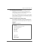
Procedure 28: Installing the cables for Ethernet LAN support
(Application Module)
This procedure assumes that your Application Module contains the
following:
¥ an MVME167-02 SBC card
¥ an MVME712M transition card
¥ a generic I/O panel
Application Modules are not shipped with the following two cables that are
essential for Ethernet LAN support:
¥ an NT7D47DA internal cable to connect the MVME712M card to the
Ethernet port of the generic I/O panel
¥ an NT7D47EA external drop cable to connect the Ethernet port of the
generic I/O panel to the Ethernet
This procedure describes how to install these cables.
1 Ensure that power to the Application Module is turned off. You may
need to perform Procedure 25: Hardware powerdown.
2 Loosen the four screws in the front of the Application Module.
3 Using the handles on each side, slide the Application Module out 9
or 10 cm (3 or 4 in.) to provide access to the connectors of the
MVME712M card.
4 Remove the eight screws holding the generic I/O panel to the rear of
the AEM and move the generic I/O panel outside the AEM so that
you can work on it.
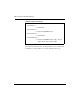
5 Connect the end marked P1 of the NT7D47DA cable to the Ethernet
connector of the MVME712M card.
6 Remove the standoff screws from the end marked P2 of the
NT7D47DA cable and connect that end to the Ethernet port at the
rear of the generic I/O panel. Use the standoff screws to attach the
P2 end to the generic I/O panel.
7 Reinstall the generic I/O panel using the eight screws removed in
step 4.