
- Meridian Controlled Routing Installation And Upgrade Guide

250 Chapter 9: Meridian Link/CCR interface cabling
553-3202-210 Standard October 1998
SDI cabling (Application Module)
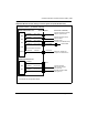
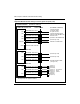
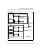
As shown in Figures 73 and 74, SDI cards (other than the NT8D41 SDI
Paddle Board) connect to the I/O panel in the Meridian 1 through an
NT8D82 RS-232 straight-through cable. From the Meridian 1 I/O panel or
SDI card on the Meridian 1 I/O panel or SDI card on the Meridian 1, an
NT7D61 cable (see Table 81 for lengths and specific codes) connects to the
Application Module at
¥ J8 on the I/O subpanel
¥ SDI LINK port on the universal I/O panel
¥ card 1 conn 3 on the generic I/O panel
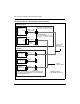
The NT7D61 cable has a 25-pin male connector for the Meridian 1 and a
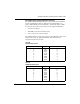
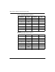
9-pin female connector for the Application Module. Table 85 lists the pin
assignments required for the cable.
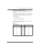
Table 85
NT7D61 cable pinout
Meridian 1 Signal AM (J8)
2
3
4
5
6
7
8
20
1
TXD
RXD
RTS
CTS
DSR
LRTN
DCD
DTR
GND
3
2
7
8
6
5
1
4
9