
- Meridian Controlled Routing Installation And Upgrade Guide


Chapter 9: Meridian Link/CCR interface cabling 171
Meridian Link Release 5C/CCR Release 3C Installation and Upgrade Guide
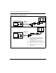
Figure 43
IPE Module Option 11 connections (Part 2)
Note 1:
Note 2:
Note 3:
It is recommended that the TD
S
/DTR card be
installed in position 1. The SDI/DCH card may be
installed in any other position except position 0
(for the CPU/Conf card).
Refer to the Meridian 1 Option 11 Installation
Guide (NTP 553-3011-210) for cross connections.
Use an NT1R03D extension cable if you need
additional length.
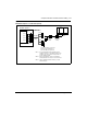
NTAK19BA
NTAK02
SDI/DCH
port 0
port 1
port 2
port 3
(
4-port
cable)
J2-9
(Note 1)
Internal
bus
port 0
port 2
port 1
port 3
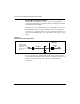
Mer
i
d
i
an 1
O
pt
i
on 11
C
onnect an
S
DI port to port 3
f
or
conshare and an ESDI port to
port 5 for AML (link 0) (Note 3)
Method 3
C
onnector
Panel
NT1R03
C
A
(extension
cable)
NT1R03AA
(octopus
cable)
1
3
5
7
IPE
Module