
Manual

96
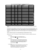
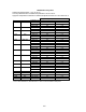
Table 1: Supported RTD Materials / Rs Sensor Resistor No.
Material R0 ALPHA
Rs
(Probe ID)
Temp Range
(deg C)
Recommended
Calib Resistor
Platinum 100 0.00385 100
-200 to +850° C
100
Platinum 1000 0.00385 1000
-200 to +630° C
1000
Platinum 100 0.00392 46.4
-200 to +630° C
100
Platinum 100 0.00391 56.2
-200 to +630° C
100
Platinum 25.5 0.00392 17.8
-200 to +630° C
100
Platinum 200 0.00385 178
-200 to +630° C
100
Platinum 470 0.00392 261
-200 to +630° C
1000
Platinum 500 0.00392 316
-200 to +630° C
1000
Platinum 500 0.00391 383
-200 to +630° C
1000
Platinum 500 0.00385 464
-200 to +630° C
1000
Platinum 1000 0.00375 1210
-50 to +500° C
1000
Platinum 100 0.00393 68.1
-200 to +962° C
100
Platinum 100 0.00389 82.5
-200 to +630° C
100
Platinum 98.129 0.00392 21.5
-200 to +600° C
100
Platinum 200 0.00392 215
-200 to +630° C
100
Copper 9.035 0.00427 12.1
-100 to +260° C
10
Copper 100 0.00427 121
-100 to +260° C
100
Nickel 100 0.00618 31.6
-60 to +160° C
100
Nickel 120 0.00672 147
-80 to +260° C
100
Iron 604 0.00518 562
-100 to +200° C
1000
Iron 908.4 0.00527 681
-100 to +200° C
1000
Iron 1816.81 0.00527 1470
-100 to +200° C
1000
10 resistor na na 14.7 Precision cal resistor na
100 resistor na na 26.1 Precision cal resistor na
1000 resistor na na 825 Precision cal resistor na
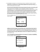
Based on the Rs value connected between pins 1 and 2, the corresponding RTD Type look up table is
utilized.
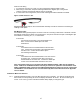
Plug connectors are available for customers that want to make up their own RTD Type standards. If no
Rs resistor is installed between pins 1 and 2, a copper wire (Rs = 0) must be wired between pins 1 and 2.
When Rs = 0 is detected, the RTD Type setting will be defaulted to the last RTD Types setting used.
This setting will display briefly at the bottom of the MFT display when the cable is attached to the RIO
module.
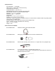
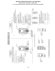
Option 1: RTD wiring styles for User Wired RTD Type with Manufacturer’s Plug
IMPORTANT: Pins 3 – 6 on the custom connector must all be connected for readings to take place!
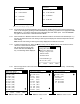
2-wire RTDs
Connect pins 3 and
4 to one wire/terminal of the
RTD. Connect pins 5 and 6 to the other wire/terminal.
3-wire RTDs
3-wire RTDs have two wires/terminals that are the same
color. Connect pin 3 to one of these wires/terminals and
connect pin 4 to the other wire/terminal of the same color.
Connect both pins 5 and
6 to the remaining, different
color wire/terminal.
4-wire RTDs
4-wire RTDs have two wires/terminals of one color and two
of another color. Connect pins 3 and 4 to each of two
wires/terminals of the same color. Connect pins 5 and 6
to each of two wires/terminals of the other color.