File No. MFT 4000:440-6 Firmware: v 4.0 & greater Nov.
MFT 4000 SERIES USER’S MANUAL Models MFT 4000 Modular Calibrator MFT 4005 Modular Calibrator with HART® Trims MFT 4010 Modular Calibrator / HART® Communicator IMPORTANT NOTICE Important information on the product is contained in this manual. Read this manual carefully and completely before operating the product. For the safety of the operator and the system, a thorough understanding of this manual is necessary before commissioning, using or maintaining the product.
MFT 4000 / 4005 / 4010 User’s Manual TABLE OF CONTENTS Subject Page MFT 4000 Overview ...................................................................................................................................1 Keypad Overview........................................................................................................................................1 Single Function Keys........................................................................................................................
TABLE OF CONTENTS, con’t Subject Page Applications ..............................................................................................................................................14 Gauge Pressure Calibration .................................................................................................................14 Differential Pressure Calibration...........................................................................................................
TABLE OF CONTENTS, con’t Subject Page Digital Polling (addresses 0 – 15)................................................................................................... 54 Manual Launch of Device Poll........................................................................................................ 54 Cloning HART devices ...................................................................................................................
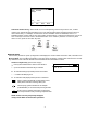
MFT 4000 SERIES OVERVIEW Module Bays (3) LCD Soft Keys Single Function Keys Dual Function Keys AC Adaptor Jack Voltage / mA Jacks HART Jacks DB-9 RS232 Connection The MFT 4000 Multi-Function Tester (MFT) is a modular calibrator with three sensor bays accommodating up to three independent pressure, temperature or special function modules. The base MFT incorporates a voltage and current meter, several keys for user interface and will display up to four measurements simultaneously.
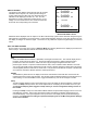
Display Contrast This key allows the user to adjust the contrast of the LCD display for ambient conditions or user preferences. Pressing and holding this key will cycle through all available contrast settings. If over-adjusted, simply release key for one second and re-press to change direction of adjustment. After adjusting Contrast, wait at least five (5) seconds before turning unit off to insure storage of new contrast setting.
Soft Keys Soft Keys (unlabled) The four white keys located below the display are the Soft Keys. The specific functions of these keys change depending on the operating mode of the MFT. Current defintions are displayed at the bottom of the LCD display.
HART 3051: PT-3456 Output: 6.5_ Inc mA Dec Next Done Numeric Only Entry Screen Alternative Numeric Entry: When the MFT is in a mode expecting numeric entry from the user, a coded numeric entry system becomes operational. Four of the main keypad buttons (see below) become active for direct number entry. For example, use this feature to enter simulation values for VMA0055, TIO0110, or RIO4000 modules, entering URV or LRV during HART communications, or setting the internal clock.
Measure DISPLAY SCREEN The display screen displays measurements from the modules installed in sensor bays S1, S2, and S3 plus the voltage or current measured by the MFT base unit. Measurements are identified on the display by lines with “S1”, “S2”, and “S3” designators for sensor module bay locations and by “V/I” for voltage or current measurements. The measured values are shown with the corresponding unit of measure. S1: VMA S2: DDN S3: RIO IV: Zero 0.000 0.000 mA PSI No Probe 0.
Pressing the Damp soft key again will remove all damping. This mode is indicated at the top of the LCD display by a “~” symbol. To select “no damping,” toggle the Damp soft key or see the Configuration Settings section of this manual. More This option takes the user to more soft key menu options.
MFT CONFIGURATION SETTINGS Press the Settings key to review the preferences on the MFT for Users, Measurements, Applications, Lockouts, Clock/Timers and Other options This will display the Settings menu. Note: Not all options will be active on all MFT models.
EJA / EJX Accuracy Utility This program is designed to aid in the calibration of the Yokogawa EJA / EJX Pressure Transmitter series. The program will calculate the maximum error based on design accuracy of the EJA / EJX and the pressure module used when performing a calibration with the MFT. Get HART Data If the EJA / EJX has HART Communications, the program will automatically read all necessary information needed to perform the calculations.
Lockouts The MFT HART Communicator can be programmed to lock out all adjustable functions or only certain functions that a supervisor may wish to control. These are Enabled or Disabled individually on the Lockout Details screen shown at right. To access, select the Lockouts option, and finally the View Details option. “Disable” on this screen means the particular menu function will not be locked out and “Enabled” means the particular menu function will be locked out once the Master Lockout is Enabled.
Important note: After the lockout code is entered, the user must cycle the power to activate the lockout mechanism! BE SURE TO SAVE THIS CODE IN A SAFE PLACE IN THE EVENT YOU FORGET THE NUMBER. ACCESS TO LOCKED-OUT FEATURES WILL BE DENIED WITHOUT THE PROPER CODE. Important note: Check Lockout status after each MFT firmware update install session to ensure desired status has been maintained.
Comm. Mode. Go to the MFT Main display and select MFT. Scroll down to the Enter PC Comm. Mode menu option and press Select. Proceed with update and cycle MFT power when the update is complete. It is recommended to use fresh batteries or an AC adaptor during update procedures. This mode will automatically time-out after approx. 2 minutes of inactivity and return to the main display. Pressing the Back soft key at this point will return to the previous screen.
Sensor Module Engineering Units Pressure Temperature PSI º Fahrenheit º Celsius Inches of Water @ 20° Celsius Inches of Water @ 60º Fahrenheit º Rankin Inches of Water @ 4º Celsius º Kelvin Ohms Kilograms/cm2 Kilopascals milli-Volts MilliBars Bars Centimeters of Water @ 20º Celsius Inches of Mercury (Referenced @ 0º C) Millimeters of Mercury (Referenced @ 0º C) oz/in2 Installation & Removal of Batteries To install or remove the six (6) AA batteries, turn the MFT face down and pull down on the loose end of t
Over Pressurization - Pressure Modules If the MFT pressure sensor is over pressurized above its full-scale pressure range, an “Over range” warning appears on the LCD above the engineering units of the affected sensor. If the applied pressure exceeds 20% of the sensor’s full-scale range, the affected pressure measurement is replaced by an “Over range” warning. If this occurs, immediately release the pressure until the MFT displays a normal reading.
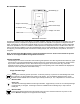
APPLICATIONS Gauge Pressure Calibration The diagram below shows two typical set-ups for calibrating a gauge pressure unit under test. If the process is a liquid, it is vital that the gauge under test be isolated and drained. If liquid enters the xDN module, damage to the sensor can occur. To use an xDN sensor, connect the pressure source to the high-pressure port of the xDN sensor. Vent the low-pressure port to atmosphere.
Differential Pressure Calibration Differential pressure gauges and transmitters can be calibrated using xDN or xGI sensor modules. The following drawing depicts a typical calibration set-up. The units under test should be isolated from the process and drained of liquids if necessary. The low-pressure port of the DP unit under test is vented to atmosphere. Do not connect the low-pressure port of an xDN sensor to the low-pressure port of the DP unit under test.
Vacuum and Absolute Pressure Calibration Vacuum calibrations can be performed with an xDN sensor module by venting the high pressure connection to atmosphere and applying the vacuum to the low pressure connection. Atmospheric pressure is the reference pressure for all vacuum measurements. Absolute pressure calibrations use a xAI sensor module. These sensor modules have an internal absolute zero reference. Simply connect the pressure (or vacuum) source to the single port on the module.
ELECTRICAL CONNECTIONS See Hazardous Area Use Section of this manual for Intrinsically Safe guidelines / restrictions. Milliamp Transmitter The diagram below depicts the proper connection for measuring the current output from a transmitter. The MFT is connected in series with the loop using standard banana jacks. Important: Use the transmitter’s working terminals to measure mA, not the TEST terminals found on some transmitters. Do not use digital communication terminals found on smart transmitters.
FIELD RECALIBRATION All pressure modules and the integral mA / V meter can be recalibrated in the field for zero, span, and linearity. The proper primary standards must be available prior to calibrating the MFT or modules. These standards should meet the accuracy requirements for your company or industry. Meriam follows the guidelines established by ANSI / NCSL Z540-1-1994 which requires that the primary standard be 4 times more accurate than the unit under test.
desired option. Use the Save soft key to choose that option. The display will then return to the main recalibration set-up menu. If you choose not to make any changes to a selected parameter, the Back soft key returns the display to the main recalibration set-up menu without making any changes. Repeat this procedure for each parameter that needs to be changed.
Exit Cal: Does not save any new calibration data and returns the user to the Measure Mode. Restart Cal: Takes the user back to the Recalibration set up screen to begin a new recalibration procedure. Save Cal: Gives the user a second opportunity to accept the recalibration data. The user can verify sensor module or mA/V calibration status by pressing the Sensr soft key from the Measure Mode display. The calibration data will show the sensor ID information and the most recent calibration date.
HAZARDOUS AREA USE The MFT 40XX Series Calibrator / Communicator is available with Intrinsically Safe Certification for use in Class I, Div I, Groups A, B, C and D Hazardous Areas. Refer to the Intrinsic Safety Control Document in the Appendix for more details. CAN /CSA-22.2 No.1010.1-92 & UL913, Fifth Edition Rev 2/21/97. The following table identifies MFT model numbers and areas of acceptable use.
MFT 4000 SERIES MODEL SPECIFIC FEATURES: MFT 4000, MFT 4005, MFT 4010 Previous sections of this manual have covered specifications and instructions that are common to all models of the MFT. The following sections address model specific instructions. ELECTRICAL CONNECTIONS by MFT Model MFT 4000 MFT MFT4005 4005 MFT 4010 MFT 4000 Calibrator Electrical connections are shrouded standard banana jacks (3/4” center) for ±50 mA/volts measurements.
Begin Calibration: Select to perform a calibration.
Cal Type: This option allows the user to select and set up the type of calibration desired and to select the location of the MFT sensor(s) that will be used for the application. Cal Type menu provides the user with a list of supported calibration types to choose from. Meas/Sim menu allows the user to select the needed MFT operation for the device under test’s input and the location of the associated sensor.
Select the Function menu option under the Meas/Sim line to select the needed MFT operation for the device under test’s input. The following screen is shown: Cal Meas/Sim: P Meas P Meas TC Meas RTD Meas VMA Meas TC Sim RTD Sim VMA Sim Up Down Select Back P Meas: is selected for P transmitter, P/I converter, P/P converter, or P switch calibrations.
P Meas: is selected for pneumatic pressure transmitter calibration T/C Meas: is selected if measuring t/c output directly – generally not used RTDMeas: is selected if measuring RTD output directly – generally not used VMA Meas: is selected if measuring mA or V using the VMA module (normally handled by the MFT’s “IV” current and voltage measurement jacks) IV Meas: is selected for P and T transmitter calibrations, P/I converter calibrations and all switch calibrations Press the Back soft key if you choose not
Pressing the Back soft key will return the MFT to the Measure Mode screen. Refer to the Calibrate section for more information. Smart Trim: The MFT 4005 and 4010 provide all measurement and HART communication features needed to trim / calibrate HART transmitters. No other handheld devices are needed. Smart Trim enables this by providing direct access to the five common HART trim commands from one MFT screen.
The screen will prompt: Take Loop offline. This notice reminds the user that the device output will not be a measurement of the actual process, and to place the receiving device or control system (such as a chart recorder, PLC, or DCS) in manual mode. Press the OK soft key to continue (or press the Abort soft key to return to the Hart Smart Trim Screen). The following screen will appear: Trim 20 ma Cal: Pump 8 AO: 20.000 mA MFT Analog Data V/I: 20.
Lower Sensor Trim: MFT 4005 and 4010 execute Lower Sensor Trims on HART devices Use the Up or Down soft key to move the selection arrow to Lower Sensor Trim, then press the Select soft key. The screen will prompt: Take Loop offline. This notice reminds the user that the device output will not be a measurement of the actual process, and to place the receiving device or control system (such as a chart recorder, PLC, or DCS) in manual mode.
Trim Upper Cal: Pump 8 PV: 99.692 InH20 MFT Upper Sensor S1: 100.00 inW20C Up Down Select Back Upper Sensor Trim Screen Apply a high pressure value to the HART device (100 inW20C shown above) and allow it to stabilize. The actual value chosen for this pressure point is at the operator’s discretion. When the S1 sensor (or whichever sensor is selected) reads a steady high pressure value, press the Trim soft key.
Cal Results: PT-307 Single variable As found Point 1 of 6 In: 0.090 inW20C Out: 3.999 mA Error: -0.096 % Pass Del Done Next Back View Calibration Results Use the Del soft key to delete the entire calibration record. Note: This Del key only removes the record from viewing by the MFT; it does not clear memory space. Connect the MFT to Meriam DMS or PC utility (pending) and use the clear MFT calibration data function to clear memory.
DOCUMENTING CALIBRATION RESULTS Overview The MFT 4000 Series of multi-function calibrators come with standard documenting capability. Documenting enables the MFT to work with manually created or DMS generated “From PC” or “stored” calibration procedures for use with specific field devices, save As found results, trim the device, save the As left results, view saved calibration results and upload saved results to Meriam’s Device Management System (DMS).
Entering Calibration Documentation Mode Press the Calibrate key to setup the MFT to document the calibration of HART or conventional devices.
Cal Cal Type: Cal Type: Meas/Sim: Function: Location: Measure: Function: Location: Up Down P P Meas S3 IV Meas IV Select Back Press the Back soft key when satisfied with the settings or if you choose not to make any changes. The MFT will then return to the Calibrate key main menu screen.
will appear and the cursor will be pointed to the offending area of the setup screen. Once the setup is correct, the following screen will appear: Cal Manual Cal Proc Manual Cal Create Procedure Up Down Select Back Manual Cal: choose this option to perform free style calibration checks by 1) applying a pressure of interest or 2) by selecting a simulation value manually. The user creates this calibration documentation as he goes.
Cal Cal Procedure Setup Continue Show Points LRV: 0.000 inW20C URV: 100.000 inW20C # upscale pts: 3 # upscale pts: 2 Adj to Limit: 5.0 Up Down Select Back Complete the information requested to help the MFT develop the cal procedure. The “Adj to Limit” entry controls how closely the applied calibration value must be to the target value as a % of the URV. If not within this limit, the MFT will not permit a Save operation. Select the Continue menu option when satisfied.
As Found Complete As Fnd: DPT-1003 Save As Fnd to AsLft Trim As left View Results Up Down Select As Found Complete As Fnd: DPT-1003 Save As Fnd to AsLft Smart Trim As left View Results Quick Cal Up Down Select Abrt As Found Complete Screen Abrt As Found Complete Screen Cal Options for Conventional Devices: Cal Options for HART Devices: Save As Fnd to AsLft – accepts the first set of saved cal data (As found) to be the As left data.
Local Indicator or Fieldbus Device Calibrations and Documentation To document the As Found and As Left condition of local indicating devices or Fieldbus devices, select Enter for the Output option on the main Cal Setup screen and then select Begin Calibration. The following screen will appear. Cal Manual Calibration S1 :10.000 inW20C Enter: 0.000 inW20C 0 Points Saved Save Entry Done Where: S1 (sensor module bay Sx): shows the input value applied to the device as measured by sensor S1.
Trim the device under test as needed and then select the As Left menu option to start the As Left documentation session. As Fnd Complete As Found: Save AsFnd to AsLft Trim As Left View Results Up Down Select Abrt As Found Complete Screen From PC (Stored) Calibration Procedures and Documentation The Stored procedure option is only available when the MFT is used in conjunction with Meriam DMS software or other compatible FCINTF software programs.
Once a tag number match is confirmed, or the user directs the MFT to use the mismatched procedure, the following screen will appear: Cal Cal: DPT1003 Cal Type PV: SN: 2138468 LRV: 0.000 inW20C URV: 100.
Cal As Fnd: DPT-1003 FAIL Save As Fnd to AsLft Smart Trim As Left View Results Quick Cal Up Down Select Abrt Calibration Options Screen for Stored Procedures Save AsFnd to AsLft – accept the first set of saved cal data (As found) to be the As left data. The Pass indicator on this screen indicates this option is acceptable. The Fail indicator lets the user know if trim operations and subsequent As left documentation are needed.
NOTE: From PC (Stored) procedures downloaded to the MFT provide data that allows the MFT to evaluate if a calibration point is in or out of calibration. MFT tracks the Pass or Fail of each point in the procedure and marks the overall As found results and As left results as either Pass or Fail as appropriate. See the Meriam DMS User’s Manual for more details on Pass / Fail and the tag data entered in DMS to support this feature.
Cal Cal Setup: Begin Calibration Procedure: Template DeviceOut: T - > Conv Cal Type: P P Meas / IV Meas Quick Cal Smart Trim View Results Clear Cal Memory Up Down Select Back Calibrate Key Main Menu Screen Normal Device Out menu options can be selected for the transmitter type of interest. The T - > indicates “Template”. The Cal Type is automatically set for the selected template. Adjustments can be made as needed to the Cal Type parameters to customize the application.
Select the Cal Type menu option and then the Loop Test menu option from the Cal Type Selection Screen. This will access the Loop Cal Type Selection Screen shown at right below. Use this screen to select the desired loop test procedure.
Cal Loop Test Set: Entered: Error: 4.000 mA 4.000 mA 0.000 % 1 points of 2 Save Entry Abrt Loop Calibration Screen If the Custom Loop Test option was selected, then the display below left is shown. Select the Create Procedure menu option to enter the Custom Loop Procedure Setup Screen shown at right below. Once this setup is complete, selecting the Continue menu option will launch the Loop Calibration Screen. Cal Manual Cal Proc Continue Show Points LRV: 4.000 mA URV: 20.
Once the As Found loop calibration test procedure is completed, the screen will change to the intermediate screen shown below. At this point, the user performs any necessary adjustments to the transmitter or troubleshoots the loop to correct errors. Once complete, select the As Left menu option to complete the As Left portion of the loop calibration.
Set Procedure to Manual and Device Out to Conv as shown above. Set Cal Type to Switch by moving the cursor arrow down to the Cal Type line and pressing the Select soft key. You will also want to set up the Meas/Sim line and the Measure line for the specific switch test desired. Meas/Sim refers to the action the MFT needs to perform for the input to the device under test (this could be Measure a pressure or temperature to a device under test or Simulate a RTD or T/C value to a device under test).
Select Begin Calibration once satisfied. The following screens appears: Cal Non-Hart Cal Begin Calibration Tag: DEFAULT Cal Non-Hart Cal Begin Calibration Measure: IV Output LRV: 19.900 Output URV: 20.000 Units: V Temperature Setup S/N: 00000 Meas/Sim: S2 LRV : 0.000 URV : 10.000 Units : C Xfer Fn : Linear Up Down Select Back Up Down Page 1 Select Back Page 2 () Use the MFT user interface to enter the Tag, S/N, and other information needed.
Where: Set Pt: theoretical set point of the switch under test Reset Pt: theoretical reset point of the switch under test Direction: contact closure on Increase or Decrease Test Reset Pt: testing reset point is optional Ramp Minutes: time for ramp when simulating RTD or T/C Start Delay: optional start delay in minutes Contact Form: Normally Open or Normally Closed options VMA (wetting): On Æ VMA0055 module wets switch circuit or Off Æ external VDC wetting LRV: Lower Range Value of test to be run (or lower li
Important Note: For Pressure Switch tests, it is very important to increase pressure slowly as the set point or reset point is approached. Quickly increasing and decreasing the pressure reduces the accuracy of the captured set point and reset points. Similarly, for simulating RTD or TC signals be sure to set the Ramp Time long enough for the LRV / URV range to insure accurate capture of set point and reset point values.
MFT 4005 with HART® Trims for Pressure and Temperature Transmitters Overview The MFT 4005 includes those HART communication functions required for analog and sensor trims for HART pressure and temperature transmitters. Normally this includes 4 mA trim, 20 mA trim, zero sensor trim, lower sensor trim, and upper sensor trim although the set can vary from device to device. No HART configuration features are available in the MFT 4005.
MFT 4010 with HART® Communications Overview The MFT 4010 includes HART communication functions that allow the user to poll, configure and maintain supported HART field device. The MFT 4010 uses a combination of Universal, Common Practice and Device Specific commands to facilitate communication with a field device.
When connecting the MFT 4010 to a loop with a resistive load greater than 250 ohms, the HART jacks may be connected across the loop + and – or to the HART device terminals. Refer to the following diagram for connecting across the loop + and -. Notice the 250 ohm adapter is not needed here. HART® COMMUNICATIONS Initial Screens / Online Mode Upon power up the MFT automatically detects if a field device is connected and attempts to establish HART communications.
If an operating HART device with address zero (0) is connected to the MFC but the “Device 0: Not Found” notification is received, the loop connections to the MFC should be carefully checked. Make sure all connections are correct and secure. Check for shorts, open circuits and multiple grounds. Determine if the loop resistance is greater than 250Ω and less than 1100Ωs. If less than 250 Ω then use the supplied 250 Ω load resistor in series with the loop (see diagram HART Connections section).
Go to the Communicator Main display and select the Offline Menu. Select List Edit Configs to view the list of stored configurations, move cursor to desired configuration and press the Select soft key. Verify the configuration is the one desired by reviewing the displayed details. When satisfied, press the Copy soft key. A complete configuration copy (all variables) will be made and a prompt to “Enter New Tag name” will be displayed. Enter the new tag number here to name the new configuration file.
FUNCTION and then the PgDn soft key. To retreat to the prior page, press FUNCTION and then PgUp. Once engaged, the PgUp and PgDn soft keys remain active until the Up or Down soft keys or FUNCTION is pressed again. List / Edit Configs: Lists all stored HART configurations by Tag Number. Once a desired tag is located with the cursor, pressing the Select soft key displays header information to help the user confirm the identity and origin of the configuration.
1151: Pump 8: Line 1 displays the model and tag number or service description of the device connected to the MFT. The model of the device is fixed and cannot be changed by the user. Device Config: Line 2 is dedicated to accessing the HART configuration menus. See the Device Setup section below for further information. PV: Displays the current primary variable’s value as reported by the digital side of the HART device.
Rerange: Allows the user to re-range the settings for Lower and Upper Range Value, set 4-20 mA values, and view Lower and Upper Span Limits. Move cursor to Rerange and press the Select soft key. The following screen will appear showing the current values for LRV, URV, LSL, and USL: Rerange Menu 1151: Pump 8 LRV: 0.00 InH20 URV: 150.00 InH20 Set 4mA Range Set 20mA Range LSL: -150.00 InH20 USL: 150.
Use the Inc / Dec soft keys to make changes. Use the Next soft key to move to the next character. Press the Done soft key when the changes are complete. A prompt will appear: Save new data? Press the Yes soft key to accept the changes. Pressing the No soft key will delete the changes and keep the previous settings. The MFT will now return to the Rerange main menu. Set 4mA Range: This option allows the user to configure the pressure value at which the HART device will read 4 mA.
The screen will display the prompt: Put Loop back online. This notice reminds the user to return the device to service. Press the OK soft key to continue. The MFT returns to the Rerange main menu screen. Press the Back soft key to return to the Sensor main menu screen. Pressing Back again will return the MFT to the Device Config screen. LSL: Lower Span Limit. This display is informational only and cannot be edited. It is the lowest output value available with the device. USL: Upper Span Limit.
Units: This option allows the user to configure the engineering units for the connected HART device. Move the cursor to Units and press the Select soft key. The screen will display the current units being used. Press the Edit soft key to change the current unit, or press Back to return to the Signal Conditioning main menu. Use the Increase and Decrease soft keys to scroll through the available engineering units. Press Done to select the new engineering unit.
Press Back to exit this screen without performing a zero trim. The screen will display the prompt: Put Loop back online. This notice reminds the user to reconnect the device under test to the receiving device. Press the OK soft key to continue to the Pressure Trim main menu screen. Pressing Back again will return the MFT to the Sensor main menu screen. Lower Trim: This option allows the user to trim the low pressure at a specific reference point. This value becomes the low sensor trim point.
reminds the user to reconnect the device under test to the receiving device. Press the OK soft key to continue to the Analog Trim main screen. Low Sensor Trim Pt: Allows the user to view the pressure value where the last Low Sensor Trim Point was referenced. See the Lower Trim section for more information. Use the Up or Down soft key to move the selection arrow to Low Sensor Trim Pt, then press the Select soft key. Use the Back key to return to the Pressure Trim main menu.
The MFT will send commands to set the HART device output to 4.000 mA. Select OK to set 4mA output. Verify the output of 4.000 mA using a reliable external multimeter. If the multimeter measurement does not confirm the 4mA, enter the trim value at the underscore ( _ ) prompt. Use the Inc & Dec key to manually adjust the value measured by the external multimeter. A prompt will appear: Save new data? Press the Yes soft key to accept the changes and implement the 4 mA trim.
Use the Up or Down key to indicate the desired Trim scale. Use the Select key to select the desired scale. Selecting 1.2 to 6.0 volts will automatically set the “Scaling Lo value:” to 1.2 and the “Scaling Hi value:” to 6.0 and a message will be displayed to “connect reference meter.” An accurate reference multimeter should be connected across the I/O resistor at this point. Select the OK menu option once this is done. The message “Setting field device output to 4 mA” will be displayed.
LOOP TEST: This option allows the user to send HART commands to the device under test to “fix” its analog output to any desired value between 4 and 20 mA, regardless of process variable value. This test is useful in determining the ability of a loop to deliver the accurate analog signals by providing a specific current output to a receiving device. Use the Down soft key to scroll to Loop Test and press the Select soft key to select. The screen will prompt: Take Loop offline.
the Analog Trim main menu screen. Pressing Back from the Analog Trim screen will return the MFT to the Config Menu screen. Select End option to return field device to original output and exit loop test. When you select End, the screen shows: Hart 1151: Pump 8 Returning Fld device to original output Inc Dec Next Done Or, press Abort soft key from loop test main screen to exit the loop test. Select Back key to return back to device Config Menu.
Private Label: Provides the device manufacturer’s name. This option is non-editable. Revisions: After selecting Revisions the screen will change and provide a menu of HART related items. Press Select to choose the item of interest. Revisions 1151: Pump 8 Hart Revision Device Revision Software Revision Final Assembly Number Up Down Select Back Revisions Main Screen Most items on this screen are non-editable, and are for informational purposes only.
Hart Output 1151: Pump 8 Polling Address: _15 Row Col Select Done The underscore will prompt the user for changes ( _ ). Use the Inc / Dec soft keys to change the value and the Next soft key to move to the next digit. Note: Acceptable polling addresses are 0 through 15.Care must be taken to insure that the new address is not already assigned to a device on the loop. Failure to do so will result in a loss of communications. When complete, press Done.
Diagnostic Menu 1151: Pump 8 Self Test Loop Test Up Down Select Back Diagnostics Main Menu Screen Self Test: Provides an overall diagnostic test of the selected HART Device. Press the Select soft key to choose the Self Test option. The screen changes as shown below. Press the Select soft key to perform a diagnostic test of the HART device. Self Test Menu 1151: Pump 8 Perform Test Test Results Up Down Select Back The symbol will appear and flash briefly, indicating the test is being performed.
Review/Edit: This function allows the user to bypass the menu system to view and/or edit variables directly from the configuration information. To enter the Review/Edit option, use the Down soft key to move the selection arrow to Review/Edit, then press the Select soft key. The Edit soft key is active only for editable parameters. To edit the displayed parameter, press the Edit soft key. The MFT will then switch to that variable’s edit screen.
DOF Memory Maintenance DOF flash memory will become fragmented after many DOF download sessions to add new or update existing DOFs. Fragmentation reduces the total number of DOFs that can be saved in memory. 600 DOFs is the nominal capacity of the flash memory). When fragmentation becomes extreme, the MFT will not accept additional DOF downloads. Periodic DOF memory maintenance will be needed to optimize DOF memory.
MFT 4010 DEVICE SPECIFIC & GENERIC HART® COMMUNICATIONS Meriam supports a growing number of Device Specific DOFs (Device Object Files). For a current listing of HART® devices with full Device Specific MFT communications support, go to http://www.meriam.com/customers/past.asp . Information found there can be sorted by clicking on any column header (manufacturer name, model number, etc.).
PC Requirements for Download Operations Meriam recommends IBM compatible Pentium I PCs or higher for download operations. The PC should have an available RS-232 port, minimum modem speed of 28K and access to Internet service. USB ports can be used with USB to Serial adapters as well. Preparing the MFT for Updating All MFT models come ready to connect to an IBM compatible PC using the DB-9 socket located at the bottom of the MFT enclosure.
RETURNING THE MFT FOR REPAIR In the event that a MFT requires service and must be returned to the factory for repair, please contact your local Meriam Representative (see list and contact information at www.meriam.com or the factory direct at the numbers listed below. DO NOT send any unit in for repair without first contacting Meriam for a Return Material Authorization (RMA) number.
APPENDIX PRODUCT SPECIFICATIONS OVERVIEW BASE UNIT: 9" L x 4.7" W x 3.2"D ABS plastic case with shock absorbing boot, 28 ozs. Three bays for measurement modules DISPLAY: 128 x 128 pixel graphic display, 2.6” x 2.6” viewable area, 5-digit resolution POWER: 6 AA alkaline batteries (1.5 V), 6 AA NiMH batteries (1.
ELECTRICAL MEASUREMENTS Current: ±50.00 mA ±0.025% FS ± 0.001% of F.S. per ° F (ref temp is 70° F) Voltage: ±50 VDC ±0.025% FS ± 0.001% of F.S. per ° F (ref temp is 70° F) MODULES: 2.3”L x 1.3”W x 2.6”D, 8.3 ozs. Positive-lock with spring-loaded sensor lock. Depress lock to release. MIN/MAX - minimum and maximum measured values are captured. Capture speed equal to current damping rate setting. HOLD - toggle function freezes display.
MODELS MFT 4000 Multi-Function Tester – Base unit for use with up to three (3) sensor modules. MFT 4005 Multi-Function Tester with HART® Trims – Base unit for use with sensor modules plus HART® trims for pressure and temperature transmitters MFT 4010 Multi-Function Tester with HART® Communications - Base unit for use with sensor modules plus HART® trims for pressure and temperature transmitters and full HART® communication capability.
MFT BASE UNIT MODEL NUMBERS (Includes CE Mark, Test Lead Kit, HART Leads (Model 4005/4010), Batteries, Universal Power Adapter, RS-232 Serial Cable, Paper User's Manual) (Note: Standard items may be different based on OEM code) (See Page 2 for Measure/Simulation Modules) Model Base Unit Model (Note: VMA0055 Module is required for 24 VDC Loop Power on all models) 4000 Calibrator - Base unit with three (3) modular sensor bays 4005 Calibrator with HART Calibration Functions; Smart Trims, Automated Calibration
Sensor Modules List PRESSURE SENSOR MODULE MODEL NUMBER, RANGE & ACCURACY Modules are Intrinsically Safe when used in accordance with Control Doc. FDN0010 1 - 10" H20 dp ± 0.1% FS from 23° F to 122° F (± 0.009 H20 dp) FDN0020 0 - 20" H20 dp ± 0.1% FS from 23° F to 122° F (± 0.020 H20 dp) "D" Series Accuracy is: ± 0.025% FS from 23° F to 122° F DDN0100 0 - 100" H20 dp ± 0.025 " H20 dp DDN0200 0 - 200" H20 dp ± 0.05 " H20 dp DDN0400 0 - 400" H20 dp ± 0.10 " H20 dp DDN2000 0 - 2000" H20 dp ± 0.
MFT ACCESSORIES LIST Sensor Modules – see list on previous page P/N A36741 Protection module for open sensor bays P/N 9B000007 Power adapter for 100 - 240 Vac, 50 / 60 Hz with US plug and int’l plug adapter kit, barrel connector P/N A900614-00011 6-pack AA alkaline batteries (1.5V), also approved for Intrinsic Safety P/N A900614-00014 6-pack AA NiMH batteries (1.2V), also approved for Intrinsic Safety P/N A37134 Energy 8 NiMH battery Charger (100-240 AC/50 or 60 Hz), Univ.
TIO0110 Module Quick Instructions For Thermocouple and milli-Volt Measurement and Simulation Safety Notice: Intrinsically Safe TIO0110 modules require the MFT Intrinsically Safe base units. The TIO module must be installed or removed in a safe area. T/C connectors must be connected to the TIO0110 module in a nonhazardous area. For more information on Intrinsically Safe operation, see the MFT User’s Manual section on this topic and see the Intrinsic Safety Control Document in the appendix.
1.3 At the TC Setup display the user can select the desired t/c from the TC Type list, select the mV to temperature conversion standard, set the temperature display resolution, select Simulate Mode or enter the User Re-Calibrate Mode. Arrow Up or Down to the desired menu option and press the Select soft key. 1.3.1 TC Type – select from T/C types E, J, K, N, T, B, R, C, D, S, M, or P. Use the Up and Down soft keys and Save key to set type. 1.3.
2.4.3 2.4.4 2.4.5 2.4.6 Select Low pt to enter the beginning test point value. Select Upr pt to enter the ending test point value. Select Steps to enter the number of test points in the procedure including the Upr pt. Select Dwell Time to choose the duration of each simulated point or chose Manual for the manual advance option. 2.5 Auto-Ramp x menu option allows pre-programmed ramp-type simulations to be set up and executed automatically by the MFT / TIO.
3.1 3.2 3.3 3.4 3.5 3.6 3.7 3.8 3.9 Offsets – Input offsets CJ gain – Gain of cold-junction compensation TC neg gain – Thermocouple negative-gain slope TC pos gain – Thermocouple positive-gain slope CJ Correction – Offset of cold-junction compensation DAC coarse gain – Coarse output DAC gain slope DAC fine gain – Fine output DAC gain slope DAC offset – DAC offset constant Full Recal – Sequences from step 3.1 to step 3.8 and stores all calibration constants. 4.
VMA0055 Module Quick Instructions For mA / V measurement, Xmitter Simulation, mA Source and V Source Notices: 1) The VMA 0055 module is not hot-swappable. To install the module, turn the MFT base unit OFF, install the VMA 0055 in any bay and turn the MFT back ON. Attempting to install the VMA module with MFT power ON will cause the MFT to shut down. Damage could occur to the MFT or module. 2) Only one VMA module is allowed to be installed at a time in MFT.
2.0 Loop Power Application The VMA will provide 24VDC Loop Power for transmitter loop circuits. The recommended wiring is depicted in the diagram below: MFT mA/V Meter + VMA Module - VOLTS COM MFT HART mA - + Transmitter Diagram 2.1 – Loop Power Connection Diagram for simple low load loop Connect the test circuit according to the Diagram 2.1. Include 250-ohm resistor for low load loops.
3.0 Manual Source and Simulation Operations– 3.1 Wire the test circuit as shown in Diagram 3.1 and 3.2 depending on the desired application: Loop Load VMA Module VOLTS COM Milliamp Receiver mA Diagram 3.1 – mA Source & V Source Connection Loop Load VMA Module - Power VOLTS COM mA + - Supply + Milliamp Receiver Diagram 3.2 – Transmitter Simulation Connection Diagram 3.2 From MFT Measure Mode, press the More soft key 3.
3.5 Select the Mode option to select from Xmitter Sim, mA Source or V Source options. Use the soft keys to move cursor Up or Down, to Select the desired option and to go Back to the VMA Main Setup Display. 3.6 From the VMA Main Setup Screen, select Start 3.7 The user will be prompted to enter the starting value with the following screen. Use the soft keys to enter the desired value. Vma Settings Current Settings Enter Output Value _ 0.
Start – Begins the desired simulation mode with the stepping parameters selected. Mode – Displays the current selected simulation mode. Select Mode to change. Low pt – Displays the starting source or simulation value. Select to enter a value. Upr pt – Displays the ending source or simulation value. Select to enter a value. Steps – Displays the number of steps to take (including the “Upr pt”). Select to change the number of steps. Dwell Time – Displays the time delay in seconds at each step.
6.0 Approvals 6.1 Intrinsically Safe by MET Laboratories, Inc per CAN/CSA-C22.2 No. 157, CAN/CSA-C22.2 No. 1010.1-92 & UL 913 Fifth Edition, Rev 2/21/97 for Class I, Division I, Groups A, B, C &D Hazardous Areas. Restrictions apply – see the Intrinsically Safe Control Document in Appendix for more details. 6.
RIO4000 Module Instructions For RTD (Resistance Temperature Detector) Measurement and Simulation when used with the MFT 4000 Series Multifunction Calibrator / HART Communicator. NOTICE: The calibrator firmware must be Version 3.42 or later in order for proper RIO4000 module operation. Safety Notice: RIO4000 modules require Intrinsically Safe MFT base unit in order to be Intrinsically Safe themselves. The RIO module must only be installed or removed in a safe area.
RIO Setup Settings & Functions Choose New Probe Display: Degrees or Ω Simulate Mode Measure Mode Selected Probe: S->Pt 100 (385) Up Down Select Back The user will be prompted: “Short the Sim. Cable Leads (clip together)” Clip the alligator clips together and then Select the OK soft key. The RIO4000 will perform a self calibration and then the user will be prompted: “Connect Sim.
Connect the leads and any necessary jumpers to the transmitter RTD sensor terminals and select the OK soft key. The RIO Simulation screen shown below will be displayed. From this screen the user can select simulation units, start a simple simulation, assign a step value change, or setup and execute automated step or ramping test procedures. RIO Simulation Simulating Start Units: C Step Value: 10.0 C Auto Step 1 Auto Step 2 Auto Step 3 Auto Ramp 1 Auto Ramp 2 Auto Ramp 3 Up 1.2.1 1.2.2 1.2.
1.2.5 Select Units to change the Auto Step x RIO Simulation simulation units. 1.2.6 Select Low pt to enter the beginning test point Auto Step 1 value. Start 1.2.7 Select Upr pt to enter the ending test point Units: F value. Low pt: 50.000 F 1.2.8 Select Steps to enter the number of test points Upr pt: 250.000 F in the procedure including the Upr pt. The Low Steps: 5 pt to Upr pt range will be evenly divide Dwell Time: 5 sec according to the number of steps selected. 1.2.
Table 1: Supported RTD Materials / Rs Sensor Resistor No. Material R0 ALPHA Platinum Platinum Platinum Platinum Platinum Platinum Platinum Platinum Platinum Platinum Platinum Platinum Platinum Platinum Platinum Copper Copper Nickel Nickel Iron Iron Iron 10 Ω resistor 100 Ω resistor 1000 Ω resistor 100 1000 100 100 25.5 200 470 500 500 500 1000 100 100 98.129 200 9.035 100 100 120 604 908.4 1816.81 na na na 0.00385 0.00385 0.00392 0.00391 0.00392 0.00385 0.00392 0.00392 0.00391 0.00385 0.00375 0.
Notes on RTD wiring 1. For maximum accuracy use 3-wire or 4-wire configurations with DIN Class A RTDs. 2. When using a 2-wire RTD, keep the lead length between the alligator clips of the generalpurpose connector and the RTD element as short as possible. 3. In 3-wire and 4-wire configurations, the wire size and length should be identical for all leads.
Measure Measure S1: No probe S1: 72.8 deg F S2: 0.000 inW20C S2: 0.000 inW20C S3: 0.00 PSIG S3: 0.00 PSIG IV: 0.000 mA IV: 0.000 mA Zero Mn/Mx Zero Mn/Mx Damp More Damp More MFT Measure Mode Display showing temperature MFT Measure Mode Display showing open RTD 2.2.2 If an RTD type is connected (depending on the Rs value), the MFT displays the measured temperature. Units can be changed by pressing the MFT Function key (and letting go) and then the appropriate Units Sensor X key.
2.2.6 Push the Up and Down soft keys to move the cursor to the desired RTD / alpha coefficient combination. Press the Select soft key to accept the selection and continue. Helpful Hint: To move page by page, press the Function key to change the soft key row to “Up Down PgUp PgDn.” Subsequent press of the Up or Down key will return the Select and Back soft key options to the display. 2.2.7 After selecting the RTD Type, the RIO Setup screen will appear as shown below.
3.1 Module Only method makes use of external precision resistors to calibrate the module’s resistance measurement. The module is set up to allow calibration using precision 10 Ω, 100 Ω, or 1000 Ω resistors rated for a total tolerance of 10 PPM. The user selects the best resistor value for the types of RTDs the RIO4000 will be used to calibrate. One connector (P/N A900442-00026) is needed for each precision resistor used.
Module Only cal can also be performed using a User Cable (p/n A900028-90500) and a precision resistor. When the User Cable is connected to the RIO4000, the RIO User Select Screen is displayed. The user can select the 10 Ω, 100 Ω, or 1000 Ω precision resistor options from the list and proceed as above. 3.
When the Error value is within acceptable limits, press the Next soft key. This moves the calibration procedure to the next calibration point. Repeat the procedure outlined above until all points are complete; when the final recalibration point is acceptable, press Next to store the data. After completion of the calibration process for 1, 3, 5, or 9 points, the MFT will inquire if the cal data should be saved. Select Yes to accept the recalibration data or No for other options.
4.0 Specifications Input impedance: > 10 megohm Warm-up time: ≤ 30 Seconds to full rated accuracy Ohm Measurement Accuracy: Temperature Effect: ≤ 0.001 ohm / °C RTD Measurement Accuracy: See RIO Accuracies Table RTD Simulation Accuracy: See RIO Accuracies Table Resolution: ± 0.
RIO4000 Accuracy Table Ambient temperature limits: -10 ºC to +50 ºC Accuracy statements are for ambient temperatures of 18º C to 28º C. Apply the Temperature Coefficient for ambient temperatures below 18º C and above 28º C Operating Temperature 18
Intrinsic Safety Document - Uncontrolled Multifunction Tester MFT 4000 Series For Controlled document see drawing sent with actual handheld 105
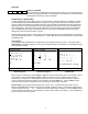
Generic DOF (HART 5 devices) “Config Menu” Process Vars Sensors “Main Menu” Device Config PV AO LRV URV %Range Analog Trim Basic Info Hart Output Diagnostics “Process Vars Menu” PV % Range AO “Sensor Menu” Rerange Signal Conditioning “Analog Trim Menu” 4mA Analog Trim 20mA Analog Trim DAC Trim Loop Test Scaled DAC Trim “Basic Info” Tag Date Descriptor Message Private Label Revisions “HART Output” Polling Address Burst Mode Select Burst Command Number Device ID Preambles Diagnostic Menu” Self Tes
1151 Rev.
3051C Rev.
EJA Rev.