9R143 Dated 3/2011 M2110L SMART LEVEL GAUGE OPERATING INSTRUCTIONS Meriam’s M2110L Smart Level Gauge is a microprocessor-based pressure sensing device with algorithms to calculate level. The various sensors provide dip- tube bubbler accommodation, or direct head level measurements. Three configurations are available: Battery, SetPoint, and Current Loop models. All models are programmable through the front keypad, to allow configuration of the gauge.
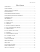
9R143 Dated 3/2011 Table of Contents LEVEL DISPLAY .......................................................................................................................... 1 SAFETY WARNINGS................................................................................................................... 2 CERTIFICATION/SAFETY/WARNINGS ................................................................................... 3 KEYPAD FUNCTIONS:.....................................................................
9R143 Dated 3/2011 LEVEL DISPLAY Indicators During normal operation, the gauge displays the level value in large numerals, and the bottom of the display shows the current Engineering Unit. The top of the display will show PRGM when the gauge is in Program Mode (flashing when “view only”). For SetPoint models, the top of the display will show SET1/SET2 to indicate activated outputs (or corresponding register opened in Program Mode).
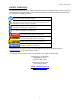
9R143 Dated 3/2011 SAFETY WARNINGS The table below defines the safety symbols, signal words and corresponding safety messages used in the manual to identify potential hazards and are intended to warn persons about hazards that could result in personal injury or equipment damage. h This is the Read Instruction Manual symbol. This symbol indicates that you must read the instruction manual. This is the Safety Alert symbol. This symbol indicates a WARNING.
9R143 Dated 3/2011 CERTIFICATION / SAFETY / WARNINGS Fire/Explosion Hazard. This instrument is not intrinsically safe. DO NOT use or service in areas that may contain flammable gas or vapors, combustible dusts or ignitable fibers where an unintended spark can cause a fire/explosion. Do not exceed the Pressure Limits listed in the Specifications section of this manual. Failure to operate within the specified pressure limit could result in death or serious injury.
9R143 Dated 3/2011 KEYPAD FUNCTIONS: The keys on the front panel perform multiple functions. Their function differs depending on whether the gauge is in Measure Mode or Program Mode. • Measure Mode is the normal operating mode for measuring and displaying level. This mode is always default after power-up or reset. • Program Mode is used to configure the various options of the gauge. This mode is denoted by a PRGM indicator on the display.
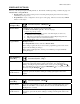
9R143 Dated 3/2011 PRGM/Enter Key PRGM Document Symbol: (PRGM/Enter→) (and EU Selection) Selects Program Mode, which allows access to the programmable registers. This key is also used to accept a new Engineering Unit selection. Program Mode Opens the selected programmable register for editing. Measure Mode When the desired value is displayed, pressing the PRGM/Enter→ key accepts and stores the value, and closes the register.
9R143 Dated 3/2011 PROGRAMMABLE REGISTER OVERVIEW All M2110L Smart Level Gauges have programmable registers that allow the gauge to be configured to fit the level measurement application. Programmable registers are numbered P0 through P11. Each register controls a specific aspect of the gauge’s performance. Beginning on page 9 is a description of all programmable registers, and instructions for their use.
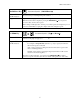
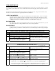
R143 Dated 3/2011 ENGINEERING UNITS The following Engineering Units are available on the M2110L Smart Level Gauge: 1. 2. 3. 4. 5. 6. 7. 8. 9. Gallons Pounds Cubic Feet Liters Percent Kilograms Cubic Meters InH2O – Inches of Water Column (density reference temperature: 20°C) User Units – User Defined Units STEP BY STEP: CHANGING ENGINEERING UNITS Step Action Display 1 Gauge should be in the normal Measure Mode. Normal Level Display. 2 Press the ENG UNITS (Up↑) key.
9R143 Dated 3/2011 ZERO REFERENCE Zeroing the gauge consists of accepting the current applied pressure value as the zero pressure reference. To set the zero reference pressure, all pressure sources should be disconnected from the gauge, and its temperature should be stable. The Smart Level Gauge displays tank level as a function of the applied pressure. This pressure is linearly offset from the zero reference value, before applying the tank level calculations.
9R143 Dated 3/2011 P0 – LOCKOUT CODE All Models This feature provides security in the Smart Gauge. It is designed to prevent unauthorized personnel from tampering with or inadvertently changing the configuration of the gauge. The lockout is controlled by a 2-digit setting in the P0 register. Once a lockout code is entered, the gauge will prompt for the lockout code before allowing any changes (similar to a “password”). Changes include Engineering Unit selection, re-zeroing, or entering Program Mode.
9R143 Dated 3/2011 P1 – TIMEOUT VALUE Battery Models Only This register sets the length of time (in minutes) for automatic shutoff. The Battery model will automatically shutoff if there is no keypad activity for this length of time. This feature can be disabled by selecting 0 in the register, which allows the gauge to remain on indefinitely, or until the ON/OFF key is pressed (battery life may be reduced).
9R143 Dated 3/2011 P2 – DAMP RATE All Models The Smart Gauge has a selectable damp rate, which is used to stabilize the display for applications with a pulsating pressure source. The damp rate setting is roughly the length of time it will take for the gauge to ramp from one stable pressure to another. The ramping is exponential, changing at a slower rate as the final value is approached. The “time constant” of the exponential equation is roughly one-fifth of the damp rate setting.
9R143 Dated 3/2011 P3 – RESIDUAL HYDROSTATIC PRESSURE All Models The M2110L Smart Level Gauge will correctly measure level when used with a dip tube or as a direct-head pressure reading of the tank’s fluid column. Register P3 is used to describe the unmeasurable pressure below the dip tube, or the additional pressure created by a “dead leg” in the direct-head piping. This register must be specified in Inches of Water Column at 20oC reference.
9R143 Dated 3/2011 3 Press the Up↑ or Down↓ keys repeatedly to scroll to the desired register. Display shows “P3”. The Zero function (Up↑ and Down↓) will reset the scroll to P0 and allow selection to continue. 4 Press PRGM/Enter→ to open the register. The display will show the current value, with the first zero flashing for edit. 5 Press the Up↑ or Down↓ keys repeatedly to scroll to the desired numeric value for the flashing digit. “_xxx”, where “_” is the digit being edited.
9R143 Dated 3/2011 P4 – FULL TANK HYDROSTATIC PRESSURE All Models This register is used by the gauge to draw a relationship between measured static pressure and actual level in volume or mass units. This register must be set to the pressure created by a FULL COLUMN of vertical fluid in the tank, in inches of water column at 20ºC reference temperature.
9R143 Dated 3/2011 P5 – SETPOINT OPTIONS SetPoint & Current Loop Models Only This register defines the output action for SetPoint and Current Loop models. Note that if an output is disabled by this register, the SetPoint value in its corresponding register (P6, P7) has no impact. Also note that a SetPoint value (P6, P7) may be 0.0, which is a viable output setting; thus, in order to disable control action, register P5 should be used to define the desired action.
9R143 Dated 3/2011 P6 and P7 – SETPOINT (SET1 and SET2) SetPoint & Current Loop Models Only SetPoint Model These registers define the pressure points at which the SPDT relays will energize. The relay will energize when the pressure exceeds its corresponding value, and de-energize when the pressure drops below the value (minus deadband; see page 17). P6 defines the SET1 relay, and P7 defines the SET2 relay.
9R143 Dated 3/2011 P8 – DEADBAND SetPoint Models Only This register is found on the SetPoint model only. It sets the adjustable deadband for the SPDT relays. Deadband can be set to 0%, 0.1, 0.2, 0.5, 1, 2, 5 and 10% of full scale. The relay will energize precisely at the value in its corresponding P6 and P7 registers on increasing level. The relay will de-energize at a value equal to the corresponding P6 and P7 register, minus the deadband value, on decreasing level.
9R143 Dated 3/2011 P9 – TANK CYLINDRICAL CAPACITY All Models The Smart Level Gauge calculates level based on measured hydrostatic pressure, by drawing a relationship between the full tank hydrostatic pressure (register P4, page 14), and the total capacity of the tank (volume or mass). The residual pressure (register P3, page 12) and tank type (register P11, page 20) are also considered in the calculations. The P9 and P10 registers together specify the tank capacity referred to above.
9R143 Dated 3/2011 P10 – TANK ENDS CAPACITY All Models The Smart Level Gauge calculates level based on measured hydrostatic pressure, by drawing a relationship between the full tank hydrostatic pressure (register P4, page 14), and the total capacity of the tank (volume or mass). The residual pressure (register P3, page 12) and tank type (register P11, page 20) are also considered in the calculations. The P9 and P10 registers together specify the tank capacity referred to above.
9R143 Dated 3/2011 P11 – TANK TYPE All Models This register identifies the type of tank application, with respect to the vertical fluid pressure measurement. Linear: The hydrostatic head change is proportional to the level change. For example, a cylindrical tank standing vertically (first tank pictured on page 19) is linear because the change in pressure produced by the fluid in the tank is proportional to the change in level (or mass).
9R143 Dated 3/2011 LOCKOUT CODE PROMPT All Models DESCRIPTION When a gauge is “locked” for security purposes, it does not allow access to change its operating state without first providing the lockout code. A gauge is “locked” by entering a lockout code in register P0 (See “STEP BY STEP: P0, LOCKOUT CODE” on page 9). After pressing a key on a locked gauge for a desired function (ZERO, ENG UNITS, PRGM), “L 00” will appear on the display, with the first 0 flashing.
9R143 Dated 3/2011 SERIAL PORT SERVICE SetPoint & Current Loop Models Only The M2110L Smart Level Gauge SetPoint models and Current Loop models provide RS-232C communication capability. To use the serial service, connect a standard “dumb terminal” (or personal computer with terminal software) as shown in the wiring diagram on page 25. Set the terminal communication for 9600 baud, 8 data bits, no parity, one stop bit, and no handshaking.
9R143 Dated 3/2011 IMPACT ON OPERATION Use of the serial port service is independent of the operating mode of the gauge, and vice versa. It is not necessary to change to Program Mode to use any of the menu’s features, including changing Engineering Units, editing programmable registers, and re-zeroing. The gauge continues its active operation regardless of the serial port service, except for the pausing explained in the next paragraph.
9R143 Dated 3/2011 ERROR CODES All Smart Gauge models have an error/message feature to inform the operator of problems with the operation or programming of the gauge. These Error Codes and messages are identified and described in the table below. ERROR DESCRIPTION “OP” Overpressure warning. The measured pressure exceeds the full scale pressure by 20% of full scale or more (high or low) .
9R143 Dated 3/2011 INSTALLATION AND WIRING The SetPoint model utilizes the multifunction terminal strip shown at the left. This terminal strip has a NEMA 1 rating. SPDT relays are not powered by the gauge internally. Jumpers from the 24Vdc, 115Vac or 230Vac power sources can be used if required. GND The Current Loop model uses a cannon connector that is designed to meet NEMA 4X requirements. The charts at the left show the terminal and wiring arrangement.
9R143 Dated 3/2011 CURRENT LOOP MODEL LOOP WIRING 24 VDC/ 50 mA Power Supply 24VDC +LOOP R SMART GAUGE +LOOP + + SMART GAUGE - - LOOP 24 VDC/ 50 mA Power Supply 24VDC -LOOP Gauge & Loop Power GROUND - R Gauge & Loop Power GROUND 3 WIRE SINKING 4 WIRE SOURCING 24VDC + LOOP SMART GAUGE - LOOP + R LOOP + Power Supply 24 VDC 20mA Power Supply 24 VDC/ 30 mA - - GROUND 4 WIRE FLOATING Note: R = Receiving Device 26
9R143 Dated 3/2011 OUTLINE DIMENSIONS PANEL MOUNTING PANEL MOUNTING CUTOUT DIMENSIONS 1. Make a ¼ DIN panel cutout per drawing. 2. Remove the two 6-32 socket head screws in the grooves at the rear of the gauge. 3. Slide the panel mount jacks out of the groove. 4. Insert the gauge through the front of the panel. 3.60" +/- 0.010 5. From the rear, insert the panel mount jacks in the grooves on the side of the gauge, and slide them firmly against the panel. (92) 6.
9R143 Dated 3/2011 PRODUCT SPECIFICATIONS DISPLAY: 4 1/2 digit, 0.6 inch (15.24 mm) LCD. TYPE & RANGE: DN: Differential Non-isolated DI Differential Isolated GI: Gauge Isolated CI Compound Isolated AI Absolute Isolated PRESSURE CONNECTIONS: 1/8" female NPT. Brass on non-isolated, 316SS on isolated sensors. INPUT POWER: SetPoint model is standard with selectable 110V AC 50/60 Hz, 220V AC 50/60 Hz, or 24V DC power. Included are an RS 232C interface and two programmable SPDT relays, rated 1.
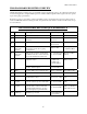
9R143 Dated 3/2011 RANGE LIMITS AND INDICATION Sensor Type Hard Under Range Under -20% 1 Soft Under Range -20 to 0% Certified Range (F.S.
9R143 Dated 3/2011 SERVICE AND CALIBRATION In the event an M2110 requires service or needs to be returned for factory recertification, battery replacement, or recalibration, please contact Meriam at the numbers listed below. The battery board should only be replaced by properly trained technicians in a controlled environment. Contact Meriam for further details DO NOT send any unit in for service without first contacting Meriam for a Return Material Authorization (RMA) number.