
Manual

32
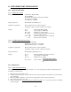
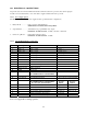
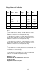
14.2 CURRENT LOOP MODEL WIRING
14.2.1 Current Loop Model Interface Connections
The Current Loop Model connections are made through the supplied interface cable. The cable is connected to an
eight (8) pin circular receptacle on the back of the unit. These connections will be defined by wire color coding of
the cable.
Pin # Wire
Color
Description Function Notes
1
BLACK
0 VDC IN Gauge Power Supply Common 0 VDC Input
2 WHITE -LOOP 4-20 mA Analog Return (+) mA output to receiver
3 RED +LOOP 4-20 mA Loop Power Input
4 GREEN +24VDC IN Gauge Power Supply Input + 24 VDC Input Nominal
5 NOT USED
6 BROWN RS232 Common RS232 interface common connection 0 VDC
7 BLUE RS232 Rx RS232 receive input connection For Serial Menu
8 ORANGE RS232 Tx RS232 transmit output connection For Serial Menu
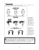
Note: See Appendix for wiring specifics.
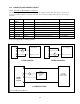
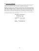
Note: R = Receiving Device
24 VDC/ 50 mA
Power Supply
+
-
Gauge & Loop Power
R
2110F
4
3
2
1
3 WIRE SINKING
24 VDC/ 50 mA
Power Supply
+
-
Gauge & Loop Power
R
2110F
4
3
2
1
4 WIRE SOURCING
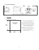
LOOP
+ Power Supply
24 VDC
20mA
-
R
4
3
2
2110F
FLOW
GAUGE
1
+
GAUGE
Power Supply
24 VDC/ 30 mA
-
4 WIRE FLOATING