
Manual

31
14.1 ELECTRICAL CONNECTIONS
Setpoint models come with a terminal block interface while the Current Loop model comes with an eight-pin
circular connector/cable interface. Note: The cable is supplied with the Current Loop model.
14.1.1 Power Supply Options
The M2110F SMART GAUGE can be supplied in three possible hardware configurations.
1. Battery Model ..………….Unit powered by internal batteries
NO EXTERNAL POWER SUPPLY REQUIRED
2. Setpoint Model …………..Unit includes two programmable relay outputs
EXTERNAL POWER SOURCE: 24 VDC, 115 VAC or 230 VAC
3. Current Loop Model …….Unit includes 4-20 mA output
EXTERNAL POWER SOURCE: 24 VDC
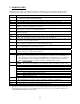
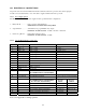
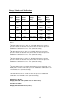
14.1.2 Setpoint Model Interface Connections
Terminal
Description Function Notes
1
SET1 / NO Relay1 output Normally open
2 SET1 / C Relay1 output Common
3 SET1 / NC Relay1 output Normally closed
4 SET2 / NO Relay2 output Normally open
5 SET2 / C Relay2 output Common
6 SET2 / NC Relay2 output Normally closed
7 No Connection None
8 RS232 Common RS232 interface common connection 0 VDC
9 RS232 Tx RS232 transmit output connection For Serial Menu
10 RS232 Rx RS232 receive input connection For Serial Menu
A
Frame Ground Earth Connection
B GND AC Ground
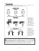
DC POWER SUPPLY CONNECTIONS
C 0 VDC Common Connect only if not using AC inputs
D +24 VDC IN +24 VDC Input Nominal Connect only if not using AC inputs
AC POWER SUPPLY CONNECTIONS
Reconnectable 115/230 Primary
115 VAC
INPUT
230 VAC
INPUT
E Reconnectable Transformer Primary Jumper E to H NC
F Reconnectable Transformer Primary Jumper F to J NC
H L2 Reconnectable Transformer Primary (See E above) L2 / 230 VAC
J Reconnectable Transformer Primary (See F above) Jumper J to K
K N Transformer Primary Fused Input Line Neutral
L L1 / L Transformer Primary Fused Input L 115 VAC L1 / 230VAC
Note: See Appendix for wiring specifics.