
Manual

12
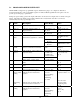
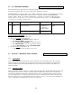
5.1 PROGRAMMABLE REGISTER LIST
All M2110F Flow Gauges have programmable registers that allow the gauge to be configured to fit the flow
measurement application. The programmable registers are numbered P0 through P10 and each register controls a
specific aspect of the gauge’s performance.
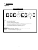
During any register editing operation the display will return to the measure mode display after one minute of keypad
activity. This will ensure that the gauge will be available for flow measurement observation even if it was
unintentionally left in the program display mode.
P#
Name Description Value Range Notes
P0 Lockout Code Lockout for security. 00 to 99 00 = Disabled.
Pg. 14
P1 Time-out Automatic shutoff in minutes of
keypad inactivity.
0 (disabled), 1, 2, 5,
10, 15, 25
Battery models only.
Pg. 14
P2 Damp Rate Exponential damping time in seconds. 0.1, 0.2, 0.5, 1, 2, 5,
10, 15, 25, 50
0.1 = No Damping.
Pg. 15
0) inH2O display
Std. InH2O @ 20ºC
Pg. 15
1) Laminar Flow
Element
LFE InH2O @ 4ºC
P3 Measurement
Mode
Identifies the primary element
characteristic (Square Root or Linear)
2) Square Root
Element
SQRT InH2O @ 60ºF
P4 Low Flow
CutOff
Minimum display value that will be
viewed on the LCD and Serial I/O.
-19999 to Max. Full
Scale
Decimal flashes when
activated.
Pg. 16
SetPoint Model: defines which relay
outputs are active.
0 = Disabled.
1 = SET1 only.
2 = SET2 only.
3 = Both enabled.
P5 SetPoint
Options
Current Loop Model: defines the
status of the 4 - 20 mA outputs.
0 = 4-20 disabled
1 = 4-20 enabled
Setpoint and Current
Loop models only.
Pg. 17
P6 SET1 Controls SET1 relay or 4.00 mA
value.
–20% to +120% FS User defined value.
Pg. 17
P7 SET2 Controls SET2 relay or 20.0 mA
value.
–20% to +120% FS User defined value.
Pg. 17
P8 Deadband Sets the amount of deadband in
percent of full scale for relays.
0 (disabled), 0.1, 0.2,
0.5, 1, 2, 5, 10%
SetPoint model only.
Pg. 19
P9 B-Coefficient /
Flow Constant
Scaling
Engineering
Units
The scaling constant required to
calibrate the flow measurement
equation.
After the entry of numeric data, access
to the units selection is allowed.
Mantissa range
+/- 9,999
Exponent Range
E+9 to E-9
Total Range
0 to 2250
A valid P9 setting is
required for P3=1 or 2.
User can scroll
through possible
engineering units.
Pg. 20
P10 C-Coefficient
Scaling
The scaling constant required to
calibrate the flow measurement
equation.
Mantissa range
+/- 9,999
Exponent Range
E+9 to E-9
Total Range
+/- 2.0
P10 required for LFE
devices.
P3 = 2 only.
Pg. 21