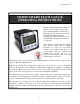
9R142 Dated 2/1/11 M2110F SMART FLOW GAUGE OPERATING INSTRUCTIONS Meriam’s M2110F Smart Flow Gauge is a microprocessor-based pressure sensing device with algorithms to calculate flow. The gauge provides laminar flow element, Accutube and Orifice Plate flow measurements. Three configurations are available: Battery, SetPoint, and Current Loop models. All models are programmable through the front keypad.
Table of Contents 1 OVERVIEW.......................................................................................................................................................4 1.1 FEATURES ...................................................................................................................................................4 1.2 MODELS ......................................................................................................................................................4 1.
9.3 9.4 9.5 9.6 9.7 9.7.1 9.7.2 9.7.3 9.7.4 9.8 9.9 9.10 10 REGISTER SECURITY .................................................................................................................................25 10.1 10.2 11 P2- DISPLAY DAMP RATE ...................................................................................................................18 P3 – MEASUREMENT MODEL .............................................................................................................
1 OVERVIEW The Meriam Instrument M2110F Gauge is a microprocessor based flow-sensing device that can be used in conjunction with a primary flow element to measure flow rate of clean dry gases. Compatible primary elements include Laminar Flow Elements (LFE), Accutube and Orifice plates. The gauge operates on the principle of measuring differential pressure across the primary element then calculating the flow rate based on user scaling input.
2 Safety Warnings The table below defines the safety symbols, signal words and corresponding safety messages used in the manual to identify potential hazards and are intended to warn persons about hazards that could result in personal injury or equipment damage. h This is the Read Instruction Manual symbol. This symbol indicates that you must read the instruction manual. This is the Safety Alert symbol. This symbol indicates a WARNING.
3 Certification / Safety / Warnings Fire/Explosion Hazard. This instrument is not intrinsically safe. DO NOT use or service in areas that may contain flammable gas or vapors, combustible dusts or ignitable fibers where an unintended spark can cause a fire/explosion. Do not exceed the Pressure Limits listed in the Specifications section of this manual. Failure to operate within the specified pressure limit could result in death or serious injury.
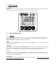
4 FRONT PANEL Warning All settings must only be entered by qualified personnel, paying particular attention to the safety and precautionary warnings. Changes to the register settings may cause incorrect flow rate display values. 4.1 4.1.1 FLOW METER DISPLAY Indicators When the gauge is in the normal measurement mode of operation it will display the Flow Rate, Engineering Unit and Time Base on the LCD display.
4.1.2 Display Refresh Rate The M2110F Flow gauge converts signal data from the differential pressure sensor at a rate of ten conversions per second depending on the operating mode of the gauge. The display is then refreshed at a rate of approximately three updates per second with a value that can be filtered by a user selectable time constant. Note: All internal calculations, analog and contact outputs, and serial interface values are updated at the maximum sampling rate. 4.1.
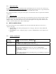
4.2.2 ENGINEERING UNITS or UP ARROW Mode of Operation Measure Mode Program Mode ENG UNITS Document Symbol: (Up↑) No function in this mode. Will generate error code if pressed. Program Mode (P# displayed): Scrolls up through the available programmable registers. Data Edit Mode: This key allows editing the register value by increasing the value of the flashing digit. As part of the P9 editing process the Engineering Unit selection can be changed.
4.2.4 PRGM or ENTER Mode of Operation PRGM Document Symbol: (PRGM/Enter→) Measure Mode Selects Program Mode, which allows access to the programmable registers P0-P10. Program Mode Program Mode (P# displayed): Opens the selected register for editing. Data Edit Mode: When the desired value is selected, pressing the PRGM/ENTER→ key accepts and stores the value.
5 PROGRAMMING IMPORTANT: Programmable registers above P0 cannot be adjusted unless the correct lockout code is entered or the lockout code is disabled.
5.1 PROGRAMMABLE REGISTER LIST All M2110F Flow Gauges have programmable registers that allow the gauge to be configured to fit the flow measurement application. The programmable registers are numbered P0 through P10 and each register controls a specific aspect of the gauge’s performance. During any register editing operation the display will return to the measure mode display after one minute of keypad activity.
6 STARTUP REQUIREMENTS The initial power up of the M2110F Flow Gauge will require register configuration to match the requirements of the application. The user will be required to enter data to properly characterize the connected flow element. This information can be obtained from the supplier of the primary element. 6.1 Power-Up Sequence After applying power to the units the gauge will perform the following functions: Sequence of power-up or reset 1.
6.4 Low Flow CutOff 1. 2. 6.5 Access P4: Low Flow CutOff Sets a flow level for which the readout LCD and serial port devices will display a clamped measurement value. • For P4 >= 0.0 (Positive or Zero) • If the measured flow value is below the Low Flow CutOff, the unit display will be forced to a zero display value. The decimal point will flash to indicate an active Low Flow CutOff. • For P4 < 0.
7.1.2 RE-ZEROING THE GAUGE / OUTPUTS ENABLED (P5=1, 2 or 3): 1. Gauge in MEASURE MODE with zero flow through primary element 2. Press the UP AND DOWN ARROW KEYS simultaneously 3.
8 ENGINEERING UNITS The Engineering units are modified as part of the P9: B-Coefficient/Flow Constant editing process. The purpose of this dependency is to require the user to enter the required unit scaling prior to selecting the engineering units. Note that the P10: C-Coefficient value may also need to be entered to provide proper scaling to the units selected. The following engineering units are available on the M2110F Flow Gauge: 1. 2. 3. 4. 5. 6. 7. 8. 9.
9 9.1 PROGRAMMABLE REGISTERS All Models P0 – LOCKOUT CODE This feature provides security in the Smart Gauge. It is designed to prevent unauthorized personnel from tampering with or inadvertently changing the configuration of the gauge. The lockout is controlled by a 2-digit setting in the P0 register. If the lockout code is active, the gauge will prompt for the lockout code before allowing any changes to register value. If the correct code is not entered when prompted, an error message will be displayed.
9.3 P2- DISPLAY DAMP RATE The Smart Gauge has a selectable damping rate, which is used to filter the display. The damp rate setting is approximately the time it will take for the gauge to ramp from one stable value to another. The filter characteristic is exponential; changing at a slower rate as the final value is approached. The “time constant” of the exponential equation is roughly one-fifth of the damp rate setting.
9.5 All Models P4 – LOW FLOW CUTOFF This register is used by the gauge to set a minimum active displayable flow value. Once the flow measurement falls below this value the LCD on the front panel and the serial port will show zero flow. This will allow the user to set a low flow threshold so that erroneous or noisy data at the low end of the measurement element will not be displayed by the gauge. A typical setting value for this register might be 0.
9.6 SetPoint & Current Loop Models Only P5 – SETPOINT OPTIONS This register defines the output action for SetPoint and Current Loop models. Note that if an output is disabled by this register the SetPoint value in its corresponding register (P6, P7) has no impact. In Measure Mode, the indicators “SET1” and/or “SET2” will illuminate when the corresponding relay is energized. The “4-20mA” indicator will illuminate when the Current Loop output is enabled.
9.7.3 Data Entry These programmable registers are entered in the current Engineering Unit used by the gauge, which are illuminated during edit of these programmable registers. For example, if the gauge is set to read in gallons/minute, and a value of 110 is put into the P6 register the SET1 relay will energize at 110 gallons. In Program Mode, the indicators “SET1”, “SET2”, and “4-20mA” will illuminate as appropriate to assist in identifying the edited register.
9.8 P8 – DEADBAND SetPoint Models Only This register is found on the SetPoint model only. The deadband can be set to 0 (disabled), 0.1, 0.2, 0.5, 1, 2, 5 and 10% of full scale flow. The relay will energize at the value in its corresponding P6 and P7 programmable registers for increasing flow values. The relay will de-energize at a value equal to the corresponding P6 and P7 register, minus the deadband value for decreasing flow values.
9.9 P9 – FLOW MEASUREMENT B-COEFFICIENT All Models The Flow Gauge calculates flow based on the differential pressure that develops across the primary element used in the flow path. By defining the characteristics of the differential pressure drop as a square root or linear function the smart gauge can calculate the flow rate from the sampled differential pressure.
4. The display shows the exponent value for P9. Press the UP or DOWN ARROWS to change the exponent digit. • Press PRGM/ENTER to enter the digit, the decimal point will flash • Press the UP or DOWN ARROWS to change the sign of the exponent • Press PRGM/ENTER to enter the exponent value • The present engineering units will be flashing. Press the UP or DOWN ARROWS to scroll through the possible units. • Press PRGM/ENTER to enter the selected units 5.
GAUGE IN MEASURE MODE 1. Press PRGM/ENTER to access P0 prompt 2. If lockout is in-active prompt will be P0 • Increment P# using UP ARROW until P10 is displayed • Press PRGM/ENTER to access the register value • Press the UP or DOWN ARROWS to change each digit • Press PRGM/ENTER to enter each digit • When the flashing decimal point is displayed, Press the UP or DOWN ARROWS to change the sign. • Press PRGM/ENTER to enter the value and sign 3. 4. The display shows the exponent value for P10.
11 SERIAL PORT SERVICE SetPoint & Current Loop Models Only The M2110F Smart Flow Gauge SetPoint and Current Loop models provide RS-232C communication capability. To use the serial service, connect a standard “dumb terminal” or personal computer with terminal software as shown in the wiring diagram on page 29. Set the terminal communication for 9600 baud, 8 data bits, no parity, one stop bit, and no handshaking. The terminal should be able to display at least 24 lines and 70 columns. 11.
While the serial port is transferring data, the other functions of the gauge are paused to allow this task to complete. In this paused state, the display is frozen and the outputs are not updating. Typically, the data transfers are very short and thus the interruption is minimal. However, selecting a register for edit will completely stop normal gauge operation, because the gauge is awaiting the operator’s input.
12 ERROR CODES All Smart Gauge models have an error/message feature to inform the operator of problems with the operation or programming of the gauge. These Error Codes and messages are identified and described in the table below. ERROR “OP” E001 E002 E003 E004 E005 E006 E007 E008 E009 E010 E011 E012 E020 E030* E110 E210* E211* E213* • DESCRIPTION Overpressure warning. The measured pressure exceeds the full-scale pressure by 20% of full scale or more.
13 SUPPLEMENTARY INFORMATION 13.1 Application Example 13.1.1 Laminar flow element Primary Element: Laminar Flow Element (LFE) Model 50MJ10-9 Nominal Air flow Range = 3.00 cubic feet/minute B-Coefficient = 4.2847E-1 C-Coefficient = -5.0523E-3 Gauge requirement: M2110F with 10.00 inH2O sensor Application requirements: Monitor airflow in units of cubic feet/minute Setup Relay outputs to detect low limit at 1.25 cu.ft/min Settings: P3 = 1 P5 = 1 P6 = 1.250 P9 = 4.285 = - E1 P10 = -5.052 = - E3 13.1.
14 INSTALLATION Differential pressure sensors have two pressure connections on the back of the gauge. The diagram below shows the correct connections to obtain the desired type of pressure measurement. The SetPoint model utilizes the multifunction terminal strip shown at the left. This terminal strip has a NEMA 1 rating. The SPDT relays are not powered internally by the gauge. Jumpers from the 24Vdc, 110Vac or 220Vac power sources can be used if required.
14.1 ELECTRICAL CONNECTIONS Setpoint models come with a terminal block interface while the Current Loop model comes with an eight-pin circular connector/cable interface. Note: The cable is supplied with the Current Loop model. 14.1.1 Power Supply Options The M2110F SMART GAUGE can be supplied in three possible hardware configurations. 1. Battery Model ..………….Unit powered by internal batteries NO EXTERNAL POWER SUPPLY REQUIRED 2. Setpoint Model …………..
14.2 CURRENT LOOP MODEL WIRING 14.2.1 Current Loop Model Interface Connections The Current Loop Model connections are made through the supplied interface cable. The cable is connected to an eight (8) pin circular receptacle on the back of the unit. These connections will be defined by wire color coding of the cable.
14.3 OUTLINE DIMENSIONS 14.3.1 1. Panel Mounting Make a ¼ DIN panel cutout per drawing. PANEL MOUNT CUTOUT 3.60 in. (92mm) 3.60 in. (92mm) 33 2. Remove the two 6-32 socket head screws in the grooves at the rear of the gauge. 3. Slide the panel mount jacks out of the groove. 4. Insert the gauge through the front of the panel. 5. From the rear, insert the panel mount jacks in the grooves on the side of the gauge, and slide them firmly against the panel. 6.
15 PRODUCT SPECIFICATIONS DISPLAY: 4 1/2 digit, 0.6 inch (15.24 mm) LCD. TYPE & RANGE: DN: Differential Non-Isolated CI: Compound Isolated GI: Gauge Isolated AI: Absolute Isolated DI: Wet/Wet Differential Isolated PRESSURE CONNECTIONS: 1/8" female NPT. Brass on non-isolated, 316SS on isolated sensors. INPUT POWER: SetPoint model is standard with selectable 110V AC 50/60 Hz, 220V AC 50/60 Hz, or 24V DC power. Included are an RS 232C interface and two programmable SPDT relays, rated 1.
Range Limits and Indication Sensor Type Hard Under Range Under -20% 1 Soft Under Range -20 to 0% Certified Range (F.S.
16 Service and Calibration In the event an M2110 requires service or needs to be returned for factory recertification, battery replacement, or recalibration, please contact Meriam at the numbers listed below. The battery board should only be replaced by properly trained technicians in a controlled environment. Contact Meriam for further details DO NOT send any unit in for service without first contacting Meriam for a Return Material Authorization (RMA) number.