
User Manual

16
Digital
Digital Digital
Digital Wiring
Wiring Wiring
Wiring Diagrams
DiagramsDiagrams
Diagrams
RS
RSRS
RS-
--
-23
2323
232
2 2
2 Communication
CommunicationCommunication
Communication
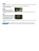
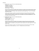
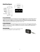
For RS-232 communication use the terminal block for power and the DB-9 connector for communications. Provide 8-
36 VDC power (20 mA minimum) by connecting to the +supply to the PWR+ terminal. Connect the –supply to the
PWR- terminal adjacent to PWR+. For communications connect the receiving device to the M1500’s DB-9 (female)
serial port (see DB-9 Pin Out Table above) or to the M1500’s RX and TX terminals. Terminal labels follow RS-232
standard TIA/EIA-232.The digital interface draws 20 mA of current or less.
RS
RSRS
RS-
--
-485 Communication
485 Communication485 Communication
485 Communication
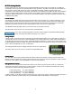
For RS-485 communication use the terminal block for power and communication. Provide 8-36 VDC power (20 mA
minimum) by connecting to the +supply to the PWR+ terminal. Connect the –supply to the PWR- terminal adjacent to
PWR+. For communications connect the receiving device to the M1500’s A and B terminals. The digital interface
draws 20 mA of current or less.
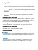
USB Communication
USB CommunicationUSB Communication
USB Communication
Connect to the USB type B female connector of the M1500. Use with
high power (500 mA) USB ports or powered USB hubs only.
5
4 3 2 1
9
8 7
6
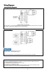
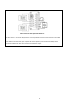
DB9 Pin Out RS-232 DCE
1 GND ---
2 RX Out
3 TX In
5 GND ---
RS
-
485
B(
-
)
RS
-
485
A
(+)
RS
-
232
RX
RS
-
232
TX
Vin(8-36V)
GND
Chassis GND