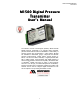
User’s Manual 9R101-E June 2012 M1500 Digital Pressure Transmitter User’s Manual The Meriam Process Technologies (Meriam) Model M1500 Digital Pressure Transmitter is a compact, NIST traceable, precision measurement instrument available in a wide variety of pressure ranges and communication / output options. Models are available for differential, gauge, compound and absolute pressure measurements. Output options include analog (420mA, 0-5V and two SPST switches) or digital (RS-232, RS485 or USB) models.
Safety Information Failure to follow all instructions could result in injury. Read, understand and follow all safety warnings and instructions provided with this product. Also, meet or exceed your employer’s safety practices. In no event shall Meriam be liable for any indirect, special, incidental, consequential or punitive damages or for any lost profits arising out of or relating to any services provided by Meriam or its affiliates.
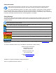
Table of Contents Certification/Safety/Warnings........................................................ 1 Introduction.................................................................................... 2 Pressure Sensor Code and Range Table ..................................... 2 CD ROM Resources...................................................................... 3 Meriam Setup Utility ...................................................................... 3 PC / M1500 Interface ..........................
User’s Manual 9R101-E June 2012 Certification/Safety/Warnings Fire/Explosion Hazard. This instrument is not intrinsically safe. DO NOT use or service in areas that may contain flammable gas or vapors, combustible dusts or ignitable fibers where an unintended spark can cause a fire/explosion. Do not exceed the Pressure Limits listed in the Specifications section of this manual. Failure to operate within the specified pressure limit could result in death or serious injury.
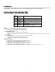
Introduction Congratulations! The M1500 is one of the most capable pressure transmitters available. Follow the instructions in this User’s Manual to set up the M1500 to perform to its full potential. Thank you for choosing Meriam. Pressure Sensor Code and Range Table 1 Model No.
CD ROM Resources Each M1500 comes with a product CD ROM that includes the following resources: - Meriam Setup Utility - Meriam Serial Protocol (MSP) Implementation Guide - USB Drivers ® - LabVIEW Drivers (VIs) Please make use of these resources as referenced in this manual. Meriam Setup Utility ® ® ® The M1500 Meriam Setup Utility runs on Microsoft Windows XP, Windows Vista and Windows 7 operating systems. Place the CD in the PC’s CD ROM drive and install the software using the installation utility.
For Digital Communication M1500s Connect the M1500 to a host PC, using the RS-232, RS-485 or USB connections provided. See the “Digital Wiring Diagrams” section of this manual for more details. Use the M1500 Meriam Setup Utility to configure the transmitter or use MSP commands (see protocol documentation on the product CD or at www.meriam.com under Resources / Application Notes). The M1500 pressure default network address is 40 (0x28 Hex) and module address is 64 (0x40 ® Hex) for MSP and LabVIEW .
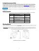
Panel Mounting Template for 4 Port Manifold (M1500-DIxxxx with optional flushing ports) Once the panel cut out is made and the mounting holes are drilled, remove the corresponding set of diagonal screws from the M1500 pressure manifold. Insert the M1500’s pressure manifold through the rear of the panel cut out. Locate the longer panel mounting screws supplied with the M1500, install them through the panel holes, and thread them into the vacated holes in M1500 pressure manifold. Tighten as needed.
Pressure Connections Failure to keep pressure below specified limits could result in death or serious injury. See section – Specifications of this manual. All pressure connections are 1/8" NPT (female). A wrench should be used on the flats of the pressure manifold to hold it securely and prevent accidental damage when installing or removing a pressure fitting. Use suitable thread tape or thread sealing compound for leak-free connections.
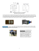
A second pressure port is present on single sensor models but has been factory sealed with an appropriate venting plug. Do not remove the plug for any reason. GI, CI, and AI units cannot be converted to other pressure types in the field. See drawing below. Permanent plug. Do Not Remove GI, CI and AI Manifold Dual Pressure Sensor Models Dual pressure sensors are available for digital communication models only. Any combination of GI, CI or AI sensors can be accommodated.
RSRS-232 RS-232 is used for point-to-point communication. The M1500 is powered through the terminal block and uses a DB-9 (female) connector or terminal block for digital communication. Terminal labels follow RS-232 standard TIA/EIA-232. See the Wiring Diagrams section for details. RSRS-485 RS-485 communication is best for multipoint networks. The M1500 can be powered and communicated with RS-232 / RS-485 Connector using either the terminal block or the DB-9 pin outs for half-duplex communication.
M1500 Analog Analog Models Analog units are set up in the field using the supplied M1500 Meriam Setup Utility and a USB type A to USB type mini-B cable. Power is provide over the USB cable for setup operations. The LED on the base of the transmitter will blink red when only the USB cable is connected.
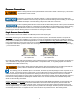
Configuration Using Meriam Setup Utility The Meriam Setup Utility application is used to configure the analog output as well as the digital outputs of the M1500. The image below is the analog setup dialog box from the program. Analog Setup Screen from Meriam Setup Utility The Pressure groupbox displays the upper and lower sensor limits (LSL/USL), current pressure reading, upper and lower range values (LRV/URV), minimum span for the range and a Zero button.
Examples: 1. Digital Output 1 is set up as shown in Meriam Setup Utility. Output action = Closed Comparison type = Between Lower Value = 0.4000 PSI Upper Value = 3.5000 PSI Reset Deadband = 0.0750 PSI As the pressure increases from 0 PSI the switch will remain open until the pressure reaches the Lower Value setpoint (0.4 PSI) at which point it will close. As the pressure continues to rise the switch will remain closed until the pressure reaches the Upper Value setpoint plus the Reset Deadband (3.5 + 0.
Zeroing the M1500 M1500 Meriam recommends zeroing the M1500 prior to use for DN, DI, GI and CI models and periodically thereafter as needed. AI models normally do not need to be zeroed prior to initial use. Two types of zeroing are supported: 1. Pressure Zero: This recommended method takes a “snapshot” of the measured pressure when the M1500 is vented to atmosphere for DN, DI, GI and CI models or, in the case of AI models, when a vacuum of less than 100 microns absolute is applied.
Wiring Diagrams Analog Wiring Diagrams Not Available for 2-wire 4-20 mA service. Can be placed on either side of the loop. 2-wire 4-20 mA, Loop Powered 24 VDC nominal – see “Power Requirements” in the Specifications section of this manual for more detail Note: Switch outputs are not available in 2-wire 4-20 mA service.
4-wire 0-5 V DC with Optional Switches 12 VDC nominal – see “Power Requirements” in the Specifications section of this manual for more detail Note: Switches are solid state, opto-couplers with SPST operation (Clare model CPC1008N). Switch circuits are isolated from each other and from the M1500 mA output..
In 4-20mA two-wire mode, stay within the operating area of the load curve for load resistance and loop voltage to assure proper performance and maintain accuracy.
Digital Wiring Diagrams RS-485 B(-) RS-485 A(+) RS-232 RX RS-232 TX 5 4 3 2 1 9 8 7 6 DB9 Pin Out 1 2 3 5 RS-232 GND RX TX GND DCE --Out In --- Vin(8-36V) GND Chassis GND RSRS-232 232 Communication For RS-232 communication use the terminal block for power and the DB-9 connector for communications. Provide 836 VDC power (20 mA minimum) by connecting to the +supply to the PWR+ terminal. Connect the –supply to the PWR- terminal adjacent to PWR+.
Recertification and Recalibration Meriam recommends annual calibration check and recertification for the M1500. Contact Meriam for this service. Periodic recalibration of M1500 Digital Pressure Transmitters may be necessary to maintain optimum performance. Meriam can also provide this service. The M1500 does support field recalibration through the Meriam Setup Utility provided on the product CD ROM.
Firmware Reflash Meriam periodically issues new operating firmware to improve M1500 operation and features. All M1500 units can be reflashed with new firmware using the Meriam Setup Utility. To install new firmware, save the new firmware file to a known location on a host PC with Internet connection. Follow the “PC / M1500 Interface” instructions in this manual, for analog or digital output versions as appropriate, and connect the M1500 to the host PC.
Feature / Command Table 19
20 Certified Measurement Range 0 to 100% FS 4.0 to 20.0 mA 0 to 100% FS 0 to 100% FS 4.0 to 20.0 mA 0 to 100% FS 3 0 to 100% FS -20 to 0% FS 3.5 to 4 mA 4.0 to 20.0 mA Value + Status 32 0 to 100% FS 4 0 to 100% FS NA 4 mA @ -14.5 PSIG 4.0 to 20.0 mA No value + Status 33 0 to 100% FS 5 0 to 100% FS NA 4 mA @ 0 PSIA 4.0 to 20.0 mA No value + Status 33 0 to 100% FS Soft Under Range -20 to 0% FS 3.5 to 4 mA Value + Status 32 -20 to 0% FS 3.
Service and Calibration In the event an M1500 requires service or needs to be returned for factory recertification or re-calibration, please contact Meriam at the numbers listed below. DO NOT send any unit in for service without first contacting Meriam for a Return Material Authorization (RMA) number. If this number has not been obtained and clearly marked on the return packaging, the unit will be returned at the shipper’s expense.
Specifications NIST Traceable Accuracy Digital: ± 0.025% of FS including all affects of linearity, repeatability, hysteresis and temperature* Analog: ± 0.035% of FS including all affects of linearity, repeatability, hysteresis and temperature* The DN0010 sensor accuracy is: Digital: ± 0.050% of FS Analog: ± 0.
Power Requirements by Communication / Output Type RS-232, RS-485: 8 – 36 VDC max., 20 mA min. USB: high power (500 mA) USB port or USB hub (PC USB ports and USB hubs with power adapters are typically high power) mA, 2-wire: 24 – 36 VDC max. (24 VDC recommended), 60 mA min. mA, 4-wire: isolated loop supply of 24 – 36 VDC max., 60 mA min. external power supply of 12 – 36 VDC max., 60 mA min. V, 4-wire: 12 – 36 VDC max., 60 mA min.