File No. 957:440-11 ACCUTUBE INSTALLATION INSTRUCTIONS 10920 Madison Avenue · Cleveland, Ohio 44102 · (216) 281-1100 · FAX (216) 281-0228 e-mail: meriam@meriam.com web site: www.meriam.
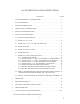
ACCUTUBE INSTALLATION INSTRUCTIONS CONTENTS PAGE ACCUTUBE MODEL NO. CONFIGURATOR................................................................3 ACCUTUBE MODELS .....................................................................................................4 1 SYSTEM CONSIDERATIONS.........................................................................................5 2 OPERATIONAL CONSIDERATIONS.............................................................................
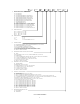
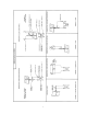
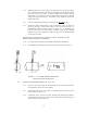
SERIES (1) LINE SIZE PROBE DIA. PROBE MATL. INSTRU. VALVES INSERT.
10A and 11A 24D and 25D 20T and 21T 33T 22L and 23L 37L Socket Drive 5 40H thru 43H 37L Gear Drive
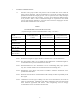
1 SYSTEM CONSIDERATIONS 1.1 Selection of the proper location and position of the Accutube flow sensor within the piping system is important. The first consideration is to locate the Accutube with proper upstream and downstream straight pipe runs. This is required to assure a fully developed symmetrical flow profile at the Accutube. Accuracy can be affected if sufficient piping is not provided. Table 1 shows recommended straight run requirements with various types of upstream flow disturbances.
1.2 Determine the position of the Accutube and indicating instrument with respect to the pipe. Selection of the entry location (i.e. in from top or bottom, etc.) is determined by considering the fluid in the pipe. Sections 1.2.1 through 1.2.4 give general requirements for Accutube position and installation, and specific recommendations for each general category of fluid (1.2.1-Liquid; 1.2.2-Gas; 1.2.3-Steam; 1.2.4-General Requirement). 1.2.1 LIQUID FLOW METERING 1.2.1.
The indicator must be placed far enough away from the Accutube to prevent thermal damage from line heat. Allow 1 ft. of uninsulated instrument piping for every 100° F of process temperature. 1.2.3.4 Slope the instrument lines to probe at an incline of approximately 1/2” per foot to prevent air entrapment. WARNING: DO NOT ATTEMPT TO FILL INSTRUMENT LINES IF SYSTEM CONNECTING LINES ARE UNDER PRESSURE. 1.2.3.5 Fill the instrument lines with water before connecting the Accutube or opening block valves. 1.2.3.
2 3 4 OPERATIONAL CONSIDERATIONS 2.1 The Accutube flow sensor is a bi-directional flow meter. It can measure flow in either direction. The Accutube head is labeled High and Low pressure as observed for normal flow directions. With reverse flow, the High-pressure signal will occur at the Lowpressure port and vice versa. Reverse flow measurement is as precise as forward flow. This unique feature allows measurement of flow that changes direction.
4.1.3 Double support type sensors require a second hole on the opposite side of the pipe. Location of this hole is important as it establishes proper alignment of the probe with respect to the flow. A common method of locating the opposite support hole is by wrapping a piece of string totally around the pipe, with the string crossing square to the pipe. The position can be marked at 1/2 the total length of the string. 4.1.4 Center the threaded weld coupling over the hole and tack weld in place. 4.1.
4.2.4 4.3 Series 10A and 11A inline sensors are bi-directional devices. They can be installed with flow in either direction through the unit. The Series 12A must be installed with the balancing valve downstream of the metering section. INSERTION FLOW SENSORS, COMPRESSION FITTING: SERIES 20T, 21T, 22L, 23L, 40H, 41H, 42H & 43H 4.3.1 Perform the general preparation steps as outlined in Section 4.1.1 through 4.1.6. 4.3.2 Slide fitting nut onto the probe with the threaded end facing the tip of the probe.
4.4 4.3.10 For maximum number of remakes, mark the fitting and nut (scribe or ink) before disassembly. Remake by tightening until marks line up again. A slight torque rise will be felt indicating the ferrule is being re-sprung into sealing position. Only after several remakes may it become necessary to advance the nut slightly past original position. This advance need only be 10° - 20° (less than 1/3 of a hex flat). 4.3.11 The Accutube is now prepared for instrument connection and operation.
4.5 4.4.4 Place the gasket on top of the weld neck flange and insert the Accutube to verify alignment of the probe and clearance. Alignment of the probe must be within the limits shown in Figure 4.1. The probe tip should clear the inside wall of the pipe by 1/16” on 12” and smaller line sizes, and 1/8” on larger line sizes (this clearance will occur within the support plug on Series 25D (see 4.4.5).
4.5.9 Lightly wrench-tighten the nut in place. Double check that all connections are tight and the insertion valve is fully open. 4.5.10 Mount the drill motor onto the drill and penetrate the pipe. The mounting assembly is now pressurized. 4.5.11 Retract the drill bit until it stops against the packing gland fitting and disassemble the drill motor from the drill bit. 4.5.12 Close the valve. 4.5.13 Slowly loosen the packing gland fitting to vent any pressure. Remove drill bit. 4.5.
4.6 4.7 4.5.26 Verify the alignment of the probe head with respect to the pipe line. The side pressure port should point directly upstream. Refer to Figure 4.1 4.5.27 The Accutube is now ready to be placed into operation. PROBE REMOVAL 4.6.1 Close the high and Low-pressure instrument valves. 4.6.2 Disconnect or modify line connections to head to allow probe removal. 4.6.3 As a precaution, hold the probe in place and adjust the safety chain to allow 2 links of slack. 4.6.
assembly weight is required for horizontal probe position on larger line sizes. 4.7.1.3 Prepare the pipe surface for welding. Tack weld the Thred-O-Let in place and verify alignment. Refer to General Installation, Sections 4.1.3 through 4.1.6. 4.7.1.4 Assemble the close nipple onto the Thred-O-Let. The close nipple is a special design nipple that serves as a drill guide and a support for the Accutube probe. 4.7.1.5 Assemble the insertion valve onto the close nipple.
the insertion flange of the packing housing. The head of the Accutube during this procedure should be oriented so that the flow arrow agrees with the flow direction within the pipe. During the initial insertion of the probe tip into the packing housing, use care not to damage the packing rings. Assemble the lower drive nuts with washers onto the insertion/retraction rods. Thread the nuts upward until the washers contact the insertion flange. 4.7.1.
4.7.2.4 The retainer is now placed atop the follower and secured loosely in place with the packing gland socket head cap screws. Do not tighten the screws at this point. 4.7.2.5 Assemble the instrument valves onto the Accutube probe head. 4.7.2.6 Insert the probe tip into the packing gland assembly. During the initial insertion, use care not to damage the packing rings. Slide the probe through the packing until the probe tip contacts the inside of the closed insertion valve.
4.7.3.3 Weld the Weld-O-Let in place in the pipe. The Weld-O-Let is to be positioned so that it is perpendicular to the centerline of the pipe and square to the surface of the pipe. The Weld-O-Let has a special designed I.D. to guide and support the drill and probe. 4.7.3.4 Assemble a weld neck flange onto the Weld-O-Let. Tack weld in place so that the flange holes straddle the pipe centerline. Verify alignment and finish the weld. 4.7.3.
4.7.3.16 Assemble the insertion/retraction rods and nuts onto the probe. The rods slip through the hole on the upper insertion bar and extend 2” out at the top. A single nut is assembled to each side of the upper insertion bar and tightened so that the rod is locked in place. Loosely assemble the upper drive nut on the insertion rod up to the lower lock nut. This is done for both rods. 4.7.3.
4.7.4.2 Lightly snug down the packing gland socket head cap screws just enough to set the packing in place and remove any clearances. Turn the hex socket head cap screws an additional 1-1/2 turns to pre-load the packing rings. Turn the screws a small amount alternately so as to tighten the assembly slowly and evenly from both sides. 4.7.4.3 Verify the instrument valves on the Accutube are closed. 4.7.4.4 Open the insertion valve.
4.7.5.3 Double support wet tap Accutubes include a specially machined insertion cone on the end of the probe. Be sure that the flow sensor is fully inserted into the opposite side support plug and not simply resting on top. Rotating the probe and/or the plug while inserting the probe will aid in alignment. Be sure to retighten the plug and provide clearance as described in 4.7.2.20 to 4.7.3.22 for socket drive wet taps or as described in 4.7.3.12 to 4.7.3.15 for gear drive wet taps. 4.7.5.
4.7.6.8 The Accutube may be left in this position (properly supported) prepared for future insertion or for removal from the wet tap assembly. There are two methods of removing the probe from the wet tap assembly. 4.7.6.8.1 Withdraw the probe completely out of the packing gland assembly and set aside. or 4.7.6.8.
4.8.1 MODELS 40H, 41H & 70H WITH DIRECT DP TRANSMITTER MOUNT HEAD 4.8.1.1 Refer to previous sections of this manual for Accutube-to-process pipe installation instructions. 4.8.1.2 The direct mount instrument head is designed to allow standard industrial DP transmitters to be bolted directly onto the Accutube head. Any transmitter with 2 1/8” center-to-center high and Low-pressure connections can be used. Height of heads is 2.42". Gaskets are supplied with the order.
4.9.1 Ducts The mounting technique for circular and rectangular ducts is most frequently the same as used for pipe in which a threaded coupling is welded in place. In instances where the duct wall is too thin to permit welding, a sheet metal flange option is available for bolt mounting. The flange is to be used with a user provided gasket or sealant between the flange and the duct. The surface of the duct where the gasket lays must be cleaned prior to application.
5 OPERATION 5.1 Once the Accutube is installed in the proper location and the instrument lines are installed to the indicator, the unit is prepared for operation. Operation of the Accutube involves setting valves in the proper sequence. Refer to Figure 5.1 in the following steps. 5.2 Verify that the operating pressure and temperature are within the Accutube and valve limitations (see Table 5). 5.3 Close Accutube valves A and B and start up the system. 5.
TABLE 5 ACCUTUBE PRESSURE/TEMPERATURE LIMITATIONS MAXIMUM PRESSURE PSIG ACCUTUBE SERIES 10A/11A Steel, brass & copper 316 SS 20T/21T 22L/23L, 40H/41H, 42H/43H 24D/25D(1) 150# flange 33T(2) 37L, 70H, 72H (2) AT (3) 250 1000 1500 250 1500 285 150 1000 TEMPERATURE °F 250 max 750 max 100 400 max 800 max 100 190 max 400 max (4) (1) Pressure / temperature on flanged series are governed by the flange rating. Flange rating options have higher capacity.
7 MAINTENANCE AND REPLACEMENT PARTS 7.1 Cleaning Accutube performance is generally not sensitive to dirt and film buildup. However, if contamination can build up to the point where internal or port hole blockage is threatened, then precautions must be taken to prevent this. One method commonly used is occasional probe removal for thorough cleaning. Purging systems are also used which on regular intervals inject air or fluid through the probe into the pipe line system, thus flushing out the probe interior.
9 FLOW CALCULATIONS Flow Equations* 1. Any Liquid Q(GPM) = 5.668 x K x Di2 x ∆ P/Sf 2. Steam or Any Gas** Q(lb/Hr) = 359.1 x K x Di2 x 3. Any Gas Q(SCFM) = 128.8 x K x Di2 x ρ x ∆P Px∆P (T + 460) x Ss Differential Pressure Equations* 1. Any Liquid Q2 x Sf ∆P (In. WC) = K2 x Di4 x 32.14 2. Steam or Any Gas** Q2 ∆P (In. WC) = K x D x ρ x 128,900 2 4 i 3. Any Gas Q2 x Ss x (T + 460) ∆P (In.
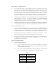
ACCUTUBE FLOW COEFFICIENT (K) TABLE 9.1 High Pressure Series 22L, 23L, 24D, 25D, 37L, 40H, 41H, 42H, 43H, 70H & 72H 1/2” DIAMETER PROBE (SER. 22L, 23L, 24D, 25D & 37L ONLY) Pipe Size K Inches 2 0.557 2 1/2 0.598 3 0.645 3 1/2 0.630 4 0.656 5 0.656 6 0.662 8 0.673 10 0.682 1” DIAMETER PROBE Pipe Size K Inches 6 0.647 8 0.678 10 0.657 12 0.677 14 0.665 16 0.691 18 0.678 20 0.705 24 0.708 30 0.664 36 0.663 42 0.672 48 0.673 60 0.685 2 3/8” DIAMETER PROBE (SER. 24D, 25D & 37L ONLY) Pipe Size K Inches 14 0.
TABLE 9.3 1/2 SERIES 10A (C.S., 316, Brass) SERIES 11A (C.S., 316, Brass, PVC) SERIES 10A (Copper Tube) 3/4 Inside Diameter (Di) For Inline Series 1 1-1/4 1-1/2 2 2-1/2 3 .622 .824 1.049 1.380 1.610 2.067 2.469 3.068 .546 .742 .957 1.278 1.500 1.939 2.323 2.900 .527 .750 1.000 1.250 1.481 1.957 2.435 2.