
User manual


www.merging.com/horus Page 21 - 54
Horus User Manual
Installing additional Horus I/O Module
Installing additional Horus I/O Cards (AD8/AD8P or DA8/DA8P)
Before you get started
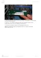
- Place your Horus unit on a hard and dry surface or mount it onto a 19” rack, and leave plenty
of room for air convection.
- In order to meet the EMC requirements of directives 89/336/EEC and 93/68/EEC, and in
order to obtain the high performance possible for the Horus unit, you must use correctly
shielded cables of good quality for all external connections when installing the Horus unit. For
the power connection, a normal unshielded power cable with a proper ground can be used.
- Make sure that your sound system is at a safe volume level.
Hardware Installation
This section will take you through installation of your Horus unit. We will describe how to mount the
I/O modules and the power, audio and digital cable connections that can be accessed on the rear
panel.
*PLEASE ENSURE THAT YOUR HORUS UNIT IS SWITCHED OFF BEFORE ATTEMPTING TO
CONNECT ANY CABLES TO THE UNIT.*
If you need to mount an I/O module at a later stage, the following procedure is used.
1. Place the shutdown Horus unit on a dry steady horizontal surface. Remove all cables
(including the power cable).
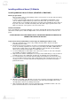
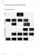
2. On the back of the Horus unit there are 6 slots for mounting the Analogue I/O cards. While all
6 slots are internally equivalent, the 3 top slots are preferably for the AD8 or AD8P Mic/Line
input modules and the lower 3 for the DA8 or DA8P line output modules. On the drawing
above, they are marked as blind Plates for I/O module slots.
3. To remove blind plates for I/O module slots, remove the 2 screws on each side of the plate.
Use a Phillips (cruciform) screwdriver tool size 2
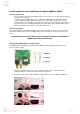
4. Only remove the number of blind plates necessary to fit the I/O module(s). If only one I/O slot
is installed, remove only 1 blind plate. If 2 I/O slots are installed, remove 2 blind plates.
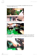
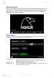
5. It is very important to insert the I/O card horizontally and carefully into the Horus unit. There
are 6 set of guides inside the Horus unit to guide the I/O cards correctly into place. Do not in
any way use force to insert the I/O card. This may damage the card. Slide card slowly as
picture below shows.
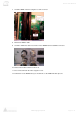
6. When the cover plate of the I/O card covers the hole created by removing the blind plate, the
2 screws from the blind plate are mounted in the sides of the I/O card. Tighten the screws
carefully and be careful not to damage the threads.
7. After inserting the I/O module, the Horus unit might need to be initialized. If this is the case,
please follow the instructions received with the I/O module.