Horus User Manual Horus User Manual Revision 0.2 www.merging.
Horus User Manual IMPORTANT SAFETY AND INSTALLATION INSTRUCTION SAVE THESE INSTRUCTIONS INSTRUCTIONS PERTAINING TO RISK OF FIRE, ELECTRIC SHOCK, OR INJURY TO PERSONS WARNING – when using electric products, basic precautions should be followed, including the following: 1. Read all of the safety and installations instructions and explanation of graphic symbols before using the product. 2. The product must be grounded.
Horus User Manual through openings. 11. The product should be serviced by qualified service personnel when: A. The power supply cord or plug has been damaged. Objects have fallen, or liquid has spilled into the product, or C. The product has been exposed to rain, or D. The product does not appear to be operating normally or exhibits a marked change in performance, or E. The product has been dropped, or the enclosure damaged. 12.
Horus User Manual IMPORTANT NOTICE: Please read the following information very carefully before attempting any installation. Failure to comply with the precise instructions may result in damage to your Merging hardware. Please read this entire section of the manual carefully before installation. STATIC DANGER NOTICE: Please note that the Horus contains delicate electronic components that can be damaged or even destroyed when exposed to static electricity.
Horus User Manual Environmental Limits System Office Environment Parameter Limits Operating Temperature +5 degrees C to +45 degrees C with the maximum rate of change not to exceed 10 degrees C per hour.
Horus User Manual Horus Warranty Information This product is warranted to be free of defects in materials and workmanship for a period of one year from the date of purchase. Merging Technologies, Inc. extends this Limited Warranty to the original purchaser. In the event of a defect or failure to confirm to this Limited warranty, Merging Technologies, Inc. will repair or replace the product without charge within sixty (60) days.
Horus User Manual INTRODUCTION TO HORUS Modular by Design Horus was designed to give its users an amazing amount of Audio I/O channels, over all the most deployed formats, while offering an unprecedented level of quality in such a small form factor.
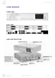
Horus User Manual HORUS HARDWARE FRONT PANEL BACK PANEL HORUS UNIT DESCRIPTION www.merging.
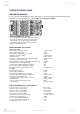
Horus User Manual HORUS BASE UNIT IOC-HORUS Specifications Case Material Front Panel Material Weight (excluding redundant PS) Dimensions (2U rack mounting) Voltage (AC) Power Consumption (Max) Front Panel TFT size/resolution Powder Coated Steel Brushed Aluminum 6.5 kg/ 14.4 lbs 483 x 320 x 89 mm 90V–260V, 47–63 Hz < 60 Watts 4.
Horus User Manual HORUS OPTIONAL CARDS IOM-HORUS AD8/AD8P These remotely controlled Mic/Line Input cards have set a new benchmark in analog circuitry design.
Horus User Manual IOM-HORUS DA8/DA8P The DA8 (up to 192kHz) and the DA8P (up to DSD) have consistently shown in testing to be the quietest multichannel D/A conversion modules available anywhere. IOM-HORUS-DA8/DA8P Key Features • Auto-mute circuitry for “no-pop” power cycling • Digitally controlled trims for line up procedures • Dynamic range of 127dB (typ.
Horus User Manual 4.
Horus User Manual IOM-HORUS-MADM/MADS The MADI Expansion card (MADM - Multimode / MADS - Singlemode) doubles the total MADI channel count to 128 inputs and 128 outputs @1FS HORUS-MADM/MADS Features • MADI Optical and Coaxial inputs and outputs • Additional 64 discrete channels of digital input and output (extended mode) at 1FS for a total of 128 inputs and outputs combined with the base unit MADI • Up to 384 kHz sampling rate as well as DSD 2.
Horus User Manual HORUS CABLES Connecting the analog audio Input cables to the AD8/AD8P modules The AD/AD8(P) modules connect the Mic/Line Inputs using DB25 D-SUB connections. Please ensure that the cables you have chosen to use, or have had made, conform to this specification before you attempt to connect them. To connect the DSUB connection to the IOC-AD8(P), line the Male cable up with the female DSUB port on the module. Then, with slight pressure, guide the connector into place.
Horus User Manual Connecting the analogue outputs cables to the DA8/DA8P modules The IOC-DA8(P) modules connect the line outputs using DB25 D-SUB connections. Please ensure that the cables you have chosen to use, or have had made, conform to this specification before you attempt to connect them. To connect the DSUB connection to the IOC-DA8(P), line the Male cable up with the female DSUB port on the module. Then, with slight pressure, guide the connector into place.
Horus User Manual Connecting the AES-EBU cable The AES ports connect the AES-EBU I/O using DB25 D-SUB connections. Please ensure that the cables you have chosen to use, or have had made, conform to this specification before you attempt to connect them. To connect the DSUB connection to the AES port, line the Male cable up with the female DSUB port on the module. Then, with slight pressure, guide the connector into place.
Horus User Manual Connecting the MADI cable The MADI port (both the standard one and the optional MADI Expansion module) can be connected using either Optical or coaxial cabling. When using Optical cabling, first ensure that you have a clean work area, as dust and debris can affect the connection if any obstruction is present in the connection. Remove the cap on both the cable and the port and slowly / firmly push the cable into the receiving port on the Horus unit until it clicks into place.
Horus User Manual Connecting the Ravenna Ethernet cables The RAVENNA port (Primary and Secondary) are RJ45 female ports. Simply take the RJ45 cable, line it up with the slot on the rear of the Horus unit and slide it into place until it clicks into its locked position. Connecting the GPIO Under development www.merging.
Horus User Manual HORUS KEY FEATURES Modular analogue interfacing Horus allows the user to choose how many Analogue inputs and Analogue outputs are needed for each unit. Horus provides a total of six universal I/O slots that can accept a combination of Mic/Line modules, and Line output cards. Users can configure their Horus with any combination of them, but installing more than 3 Mic/Line modules requires to install the Horus Redundant Power option.
Horus User Manual AES-EBU Coming as standard (as the MADI 1 module) are 3 x D-SUB25 connectors providing 24 channels (12 AES pairs) of AES-EBU I/O. Signal routing paradigm Horus is quite possibly the most flexible audio interface ever designed. Users can literally route any input signal to any output module. Better yet, it can route any input signal to any combination of output modules. Routable in blocks of 8 channels, a user can send 8 Mic Inputs to 8 AES outputs.
Horus User Manual Installing additional Horus I/O Module Installing additional Horus I/O Cards (AD8/AD8P or DA8/DA8P) Before you get started Place your Horus unit on a hard and dry surface or mount it onto a 19” rack, and leave plenty of room for air convection.
Horus User Manual Installing additional Horus MADI Extension Module (MADM or MADS) Before you get started - Place your Horus unit on a hard and dry surface or mount it onto a 19” rack, and leave plenty of room for air convection. - In order to meet the EMC requirements of directives 89/336/EEC and 93/68/EEC, and in order to obtain the high performance possible for the Horus unit, you must use correctly shielded cables of good quality for all external connections when installing the Horus unit.
Horus User Manual 3. Open the Horus top panel, remove the AD8/AD8P or D/A8/DA8P modules that could be obstructing the MADI module access 4. Disconnect the ribbon cable carefully 5. Screw the 2 spacers onto the MADI 1 / AES board 6. Carefully slide the MADI extension board so that the output connectors come out of the Horus back panel. You will need to do so with an angle that should allow you to push and fit into the header of the MADI 1 card (below).
Horus User Manual 7. Screw the MADI extension using the 2 screws received 8. Fix back the Ribbon cable 9. Screw the 2 BNC nuts at the back of the Horus MADI Extension I/O BNC connectors 10. Put back the modules that were taken out 11. Close and screw back the Horus top panel cover 12. Power back on the HORUS and you should now see the MADI 2 module present www.merging.
Horus User Manual Installing the Merging PCIe Ethernet Controller Card NET-MSC-GBEX1 Detailed steps on how to fit the NET-MSC-GBEX1 PCIe card in your PC machine. 1. Power down your PC and switch it off at the wall. Remove the screws holding the top or sides of the case on and carefully slide off the panel. 2. Wearing an anti-static wristband is preferable whenever working with sensitive electrical equipment.
Horus User Manual 5. Push down gently at first, ensuring you have the pins lined up correctly with the slot, and then apply more force to slot the card home. 6. Replace the screw holding the backing plate in place and check that the card sits securely. Finally, replace the sides of your case and plug your machine back in. 6.
Horus User Manual Horus Power On Connecting the Power Cable The Horus unit runs on 85-240 V, 50-60 Hz AC voltage. Excessive voltages can seriously damage the Horus unit, so make sure that your AC power matches the voltage of your Horus unit. When you connect the power use the cable you received together with your Horus unit and plug it into a grounded outlet. For safety and EMC reasons, and to prevent audio hum, the system must be properly grounded.
Horus User Manual HORUS TOUCH SCREEN CONTROL INTERFACE Horus Menu Hierarchy www.merging.
Horus User Manual Main Home Screen This is the screen which you will see after the Horus completes its boot sequence. From here you can get to all the other menus for the setup and use of the Horus. If at any time you want to return to the Main Screen, you can press the Merging Logo in the bottom left-hand corner to come back out to the Main Screen. The screen also has access to the 5 main sections of the Horus menu: Monitor, Meters, IO & Sync, PreAmp and Setup.
Horus User Manual IO & Sync Menu The IO and Synchronization menu is where the user can select the source of the Horus reference clock. It is essential that these settings are configured correctly in order to ensure a clean audio signal through the Horus unit. Reference Source Choose which sync source is desired by pressing on the respective Reference source.
Horus User Manual REFS Menu (I/O & Sync) This Sub Page menu is where you can visualize the Deviation and Jitter of the External Reference, as measured by the Horus synchronization circuitry. Frequency: The long-term measured Frequency (in Hz) and deviation in ppm (parts per million) between the signal the unit is locked on and the internal reference.
Horus User Manual All Active: Will select all 8 input channels for function and level grouping Non-active: Users can adjust the input settings and level for the selected channel only Gain When in Mic, the input level range allows setting the Mic Preamplifier’s Gain from -10.0 dB to +60.0 dB. In the range from -10 to 0 dB, a 10 dB Pad is actually inserted. When in Line, the input level range allows the Line Input Sensitivity to be adjusted from +24 dBu down to + 4 dBu for 0 dBFS.
Horus User Manual System Info (Set Up): In this sub menu you will find details on the Horus internals; current consumption, voltage, temperature, fan speed, serial number and the firmware version currently installed. Backlight: Dim active will darken the Horus display’s luminosity. Does in turn also save some power and hence some internally generated heat… Cooling Mode: Settings for either Low, Mid or High Cooling. This will affect the speed of fan in reference to the internally measured temperature.
Horus User Manual Advanced (Set Up): ASIO/CoreAudio Clock Setting can be set to On or Off Screensaver: The Horus touch screen screensaver can be set to 15 minutes, 30 minutes, 1 hour or disabled Formats Menu (Setup) Sample Rate: Select the Horus Sampling Rate 44.1 kHz - 48 kHz - 88.2 kHz – 176.4 kHz - 192 kHz - DXD - DSD Note: The available Sampling Rates depend on the Horus Analog modules cards. Only Premium Analog modules offer support beyond 192 kHz. Frame Rate: TimeCode Frame Rate selector (23.
Horus User Manual Modules Menu (Setup) Module menu will show the available Horus Module that your Horus has in its configuration Selecting one of the Modules described below will open the Module I/O configuration menu Monitor Shortcut to the Monitor page described above. A/D N The A/D buttons, which become active if you have 1 or more AD8(P)modules installed in the Horus unit, allow access to the Input controls.
Horus User Manual Modules: MADI Sub-Menu MADI 1 port comes as standard with each Horus. MADI 2 will be listed as “EMPTY” in Horus units that are not fitted with the optional MADI expansion card Mode: Sets the MADI mode to either “Standard” (56 audio channels) or “Extended” (64 channels). To determine which setting(s) you are able to use, please consult the user manual of the device you are connecting the Horus to in order to see which (if not both) formats it complies with.
Horus User Manual Modules: A/D - AES Sub-Menu Serial Number: This is the place you numbers without having to unslot them or open can access all your Modules serial the box Type: Module Type description Input: Enabling Visible to Ravenna will allow Ravenna to “see” and use the I/O Connections (seen under the Auto-Connect utility).
Horus User Manual Modules: Loopback Transparency Check: This is a Debug Utility tool that verifies the bits transparency of the audio path On: Transparency check enabled Off: Loopback mode enabled Word Length: Word length of the digital audio data signal (16 bits or 24 bits) Status: Green: Path transparency valid Black: Path is not transparent Numbering: indicates the number of discontinuity measured Latency: Output to Input delay in samples Input: Enabling Visible to Ravenna will allow Ravenna t
Horus User Manual Routing Menu (Setup) Module routing menu describes where the signal for each module in the Horus is coming from. Each button will go to a sub-menu that allows the user to change the origin of the signal to that specific module. For instance, the Monitor Button in the Routing menu will allow the user to change the routing to the monitor. Choices are made in blocks of 8 channels (except for the Monitor, which is a Stereo signal).
Horus User Manual * All routing in the Horus is currently achieved using banks of 8 channels* None: Sets the module so that it does not receive a signal from anywhere. Digital Mute will be output. Ravenna: Connects the module to the RAVENNA network and allows any other RAVENNA device to send signal to it. AES 1-3: Sets the module being configured to receive signal from any of the 3 banks of 4xAES-EBU input pairs.
Horus User Manual HORUS Web Control access Installing and accessing the Horus Control interface remotely To control and view your Horus remotely with a web browser make sure that you are using one of the Internet browsers below: Google Chrome, Mozilla Firefox, Opera, Apple Safari. * Microsoft Internet Explorer is not yet supported * Then take the following steps: 1) If you did not install Pyramix v8 proceed from step 2 to 3.
Horus User Manual Figure 2 Horus Web Access All of the Web access menu pages will be similar to the ones on the Horus TFT display except for the PREAMP and Network menus.
Horus User Manual Network web menu The Network page allows users to personalize a name for the Horus unit. Figure4 Horus Network Web menu The Horus embedded User Manual Users can open the Horus embedded User Manual by clicking on the ? sign at the bottom left of your browser. This will overlay the Horus User Manual on your Web control access page. Figure5 Horus Embedded User Manual www.merging.
Horus User Manual HORUS SET UP EXAMPLES Horus Standalone Converter: Pyramix & Internal Routing Pyramix in Live – Stage Box www.merging.
Horus User Manual Pyramix in Live – Technical Rehearsal www.merging.
Horus User Manual Horus Converter with Pyramix V8 & Ravenna Standard setup Standalone audio router replacement www.merging.
Horus User Manual Network Audio Total Redundancy www.merging.
Horus User Manual Live – Total Redundant Stage Box Concert / Arena / Event – Redundant www.merging.
Horus User Manual Horus with Ravenna Pyramix V8 Native: Live – Mobile Recording www.merging.
Horus User Manual Horus Firmware update procedure 1) Download the latest available firmware, available at http://www.merging.com/horus/download 2) Make sure that the .bin downloaded firmware file on a PC that is on the same network than your Horus. (Users that have received a .
Horus User Manual 7) Open the MTDiscovery tool, you should see a device called “Horus in Maintenance Mode”, double click on it. MT Discovery is installed with Pyramix v8. But it can also be downloaded from Horus Standalone users at http://www.merging.com/horus/download Note: If you do not see the Horus Maintenance Mode entry, try to reboot Horus in Maintenance mode and verify your Horus Ethernet Connection to the MassCore GB Ethernet Card.
Horus User Manual Note: If your web browser does not open on the firmware upgrade page, clear your browser history and re-open the Horus page by Double Clicking on the “Horus in Maintenance Mode” entry in MT Discovery. 9) Click on “Select File” and choose the file (.bin) that you have previously unzipped on your disk 10) Click on “Update Device” (after a while, you can see some messages on the TFT screen).
Horus User Manual IMPORTANT: If the Firmware update procedure fails, redo the Firmware update procedure by pressing the “Try Again’ Button (it will bring you back to step 7) Avoid powering down the HORUS if the firmware update has failed. It is mandatory that you try to re-update the firmware, refresh the online web page if necessary. Or go back to your browser previous page and choose again the firmware and re-update it. If you do not proceed this way your Horus might no longer start up.
Horus User Manual Horus Troubleshooting How to provide Merging Support with a debug dump file of the Horus Dump procedure: 1. Connect the Horus with the Ethernet link to your system 2. Open a web browser (e.g. Google Chrome) and make sure that you type in your Horus Ip address 3. This should open the Main Horus Page (you could also have opened the Horus Web page from the MT Discovery tool) 4. Follow up the ip address with the /debug/syslog as in example below 169.254.60/debug/syslog 5.