
User`s manual


2: Mainboard Installation
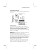
Infrared Port
You can connect an infrared port to the mainboard. You can
purchase this option from third-party vendors.
Pin Signal Pin Signal
1 NC 2 KEY
3 +5V 4 GND
5 IRTX 6 IRRX
1. Locate the infrared port SIR1 header on the mainboard.
2. If you are adding an infrared port, connect the ribbon cable
from the port to the SIR1 header and then secure the port to an
appropriate place in your system chassis.
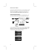
Aux-In Connection
If you have installed a secondary CD-ROM drive or DVD-ROM
drive, you can connect the drive audio cable to the onboard sound
system. On the mainboard, locate the 4-pin auxiliary audio-in
header AUX_IN1, and connect the cable to the connector.
Pin Signal Pin Signal
1 AUX_L 2 AUD_GND
3 AUD_GND 4 AUX_R
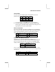
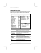
Onboard LAN LED Connections
If you have a set indicator LEDs for the onboard LAN
communication, you can connect the LED cable to the header J1.
Pins 1-2 are for Link LED. Pins 3-4 are for 10/100 Mbps mode
LED, the onboard LAN run in 100 Mbps mode when the LED lit.
Function Jumper Setting
Normal Short Pins 1-2 & 3-4
LAN LED Open Pins 1-2 & 3-4
Notice: Usually, keep the jumper setting as Normal (Short Pins 1-2 & 3-
4); only turn to LAN LED (Open Pins 1-2 and 3-4) for actuating the LAN
LED indicator.
Pin Signal Pin Signal
1 Link LED 2 GND
3 GND 4 10/100 Mbps mode LED
19