
User`s manual


2: Mainboard Installation
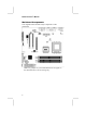
Connect the case switches and indicator LEDs to the PANEL1
header.
Pin Signal Pin Signal
1 HDD_LED_P 2 PWR/ACPI LED
3 HDD_LED_N 4 PWR/ACPI LED
5 RESET 6 POWER BUTTON
7 RESET 8 POWER BUTTON
9 KEY 10 KEY
If there are a headphone jack or/and a microphone jack on the front
panel, connect the cables to the AUDIO1 header on the mainboard.
Pin Signal Pin Signal
1 MIC 2 GND
3 MIC-P 4 VCC
5 AUD_FPOUT_R 6 AUD_RFT_R
7 NC 8 KEY
9 AUD_FPOUT_L 10 AUD_RFT_L
Note: If you want to connect the front panel sound jack, you
have to remove jumper caps of Pin(5-6) and Pin(9-10) from the
AUDIO1 header.
15