
User`s manual

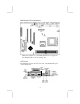
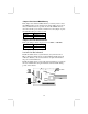


Connect the power connector from the power supply to the ATX1
connector on the mainboard. CPUPW1 is the CPU Vcore power
connector.
If there is a cooling fan installed in the system chassis, connect the
cable from the cooling fan to the SYSFAN1 fan power connector
on the mainboard.
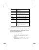
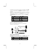
Connect the case switches and indicator LEDs to the PANEL1
header.
Pin Signal Pin Signal
1 HDD_LED_P 2 PWR/ACPI LED
3 HDD_LED_N 4 PWR/ACPI LED
5 RESET 6 POWER BUTTON
7 RESET 8 POWER BUTTON
9 NC 10 KEY
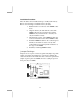
Connecting Optional Devices
Refer to the following for information on connecting the
mainboard’s optional devices:
1
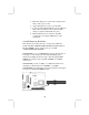
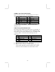
SPK1: Speaker Connector
Connect the cable from the PC speaker to the SPK1 header on the
mainboard.
Pin Signal Pin Signal
1 +5V 2 NC
3 GND 4 SPKR
SPK1
1
1
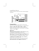
USB3
SIR1
1
AUDIO2
13