
Service manual


EDI DIAGNOSIS
SERVICE MANUAL NUMBER 22
90-860074--1 FEBRUARY 2002 Page 5E-23
TEST DESCRIPTION:
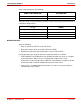
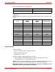
Verify continuity between the following pins:
ECM 68 PIN CONNECTOR
2 TERMINAL CONNECTOR AT ECT
14 1
33 2
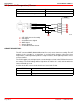
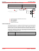
Verify the sensor resistance between the two ECT sensor terminals as a function of
temperatures:
NOTE: Stabilization time before each measurement should be at least 10 minutes in water.
TEMPERATURE
°C (°F)
RESISTANCE
(kOhm)
MAXIMUM MEASURE-
MENT Current (mA)
–30 (–22) 22.2 - 31.8 0.2
–10 (13) 8.29 - 10.61 0.4
20 (67) 2.28 - 2.72 1.0
50 (122) 0.751 - 0.901 1.5
80 (175) 0.291 - 0.353 2.0
120 (247) 0.104 - 0.120 3.0
DIAGNOSTIC HELP:
Verify the following:
• Open or short in the CKT Pin 14 or CKT Pin 33.
• Bent terminal or pin at the ECT or ECM.
• Defective ECT or ECM.
ECT failure influences engine performance as follows:
• FUEL QUANTITY ACTUATION: Maximum engine rpm is 80% of the normal
operating range (35% of fuel quantity reduction).
• LOW IDLE SETPOINT VALUE: The engine operates at 850 rpm for the first 300
seconds after engine start up and then goes to 700 rpm (normal idle).
• TIMING ADVANCE: The system adds 3 to 4 degrees of timing throughout the engine
operating range (engine is noisier).
• GLOW PLUG LAMP: Even if the engine is not equipped with glow plugs, the glow
plug lamp flashes at each start up for 12 seconds.
IMPORTANT: Torque the ECT sensor to specification when replacing.