
Service manual


ENGINE MECHANICAL
SERVICE MANUAL NUMBER 22
90-860074--1 FEBRUARY 2002 Page 3A-115
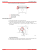
IMPORTANT: The combustion chamber recess and numbers on connecting rod must
face injector and camshaft side of the engine.
4. Turn crankshaft to position crank pin away from cylinder so connecting rod will not
damage it during installation.
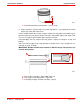
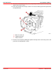
5. Using ring compressor, install piston by tapping on piston-top with a suitable device.
70300
a
a-Ring Compressor
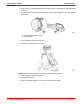
6. Insert bearing shells into connecting rod and matching rod cap. Lubricate bearings and
crank pin with a mixture of 20% SAE 30W engine oil and 80% Needle Bearing Assembly
Lubricant.
7. Align connecting rod with crankshaft journal and tap on piston top until rod bearing
contacts journal. Do NOT scratch or nick crankshaft journal.
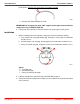
8. Ensure that corresponding numbers on rod cap and connecting rod are the same and
are on the same (camshaft) side.
9. Install rod cap, lubricate bolt threads with Needle Bearing Assembly Lubricant. Torque
bolts evenly to 29.4 Nm + 60 degrees (21 lb-ft + 60 degrees).
10. Ensure that connecting rod assembly and crank pin are not binding and that there is
proper side-to-side movement.
11. Install remaining piston and connecting rod assemblies.
12. Measure for head gasket thickness as previously outlined.
13. Refer to appropriate Sections and complete the engine assembly.