Contents Before driving Introduction 2 Instrumentation 6 Controls and features Seating and safety restraints 21 113 Starting and driving Starting 143 Driving 148 Roadside emergencies 176 Servicing Maintenance and care 198 Capacities and specifications 246 Customer assistance 255 Reporting safety defects 267 Index 268 All rights reserved.
Introduction The following warning may be required by California law: CALIFORNIA Proposition 65 Warning WARNING: Engine exhaust, some of its constituents, and certain vehicle components contain or emit chemicals known to the State of California to cause cancer and birth defects or other reproductive harm.
Introduction BREAKING-IN YOUR VEHICLE There are no particular breaking-in rules for your vehicle. During the first 1 600 km (1 000 miles) of driving, vary speeds frequently. This is necessary to give the moving parts a chance to break in. INFORMATION ABOUT THIS GUIDE The information found in this guide was in effect at the time of printing. Ford may change the contents without notice and without incurring obligation.
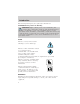
Introduction These are some of the symbols you may see on your vehicle.
Introduction Vehicle Symbol Glossary Child Safety Door Lock/Unlock Interior Luggage Compartment Release Symbol Panic Alarm Engine Oil Engine Coolant Engine Coolant Temperature Do Not Open When Hot Battery Avoid Smoking, Flames, or Sparks Battery Acid Explosive Gas Fan Warning Power Steering Fluid Maintain Correct Fluid Level Emission System Engine Air Filter Passenger Compartment Air Filter Jack MAX MIN Check fuel cap 5
Instrumentation Instrument cluster (pg. 8) Headlamp control (pg. 21) Speed control (pg. 78) Instrument panel dimmer switch (pg. 22) Reverse sensing system* (pg. 33) DOOR AJAR CHECK GAGE 4 3 H CHECK ENGINE F ABS 50 40 RPMx1000 30 20 1 FUEL RESET 6 60 70 80 0 0 0 80 100 10 0 40 140 000000 160 100 180 20 H SPEED CONT L 110 4WD HIGH km/h 120 MPH ! E 90 120 60 2 C 5 H 4WD LOW L CHECK SUSP O/D OFF RSM OFF ON SET ACC OFF COAST OFF Tilt steering wheel lever (pg.
Instrumentation Electronic sound system (pg. 36) Gearshift (includes overdrive button) (pg. 156) Rear wiper/washer control (pg. 83) Rear window defroster control (pg. 33) OD ON/OFF OFF VOL - PUSH ON AM 4x4 AUTO HIGH LOW BASS CLK ST FM1 TREB BAL FADE FM SEEK SCAN SIDE REW EJ TUNE 1 2 3 4 5 R. WIPE HI PUSH TAPE AMS 1-2 FF 6 OFF A/C MAX A/C 4wd control* (pg. 159) Climate control system (pg. 22) Fog lamp control* (pg.
Instrumentation WARNING LIGHTS AND CHIMES DOOR AJAR CHECK GAGE 4 3 H CHECK ENGINE 5 6 20 1 CHECK FUEL CAP F E ABS 60 70 80 0 0 0 80 100 10 0 ! BRAKE P 40 90 120 60 30 2 C 50 40 RPMx1000 140 000000 20 MPH R N D 2 1 160 100 180 H 4WD HIGH km/h 120 THEFT SPEED CONT L 110 H CHECK SUSP 4WD LOW L O/D OFF Check engine Your vehicle is equipped with a computer that monitors the engine’s CHECK emission control system.
Instrumentation These temporary malfunctions can be corrected by filling the fuel tank with high quality fuel of the recommended octane and/or properly installing and securely tightening the gas cap. After three driving cycles without these or any other temporary malfunctions present, the Check Engine light should turn off. (A driving cycle consists of a cold engine startup followed by mixed city/highway driving.) No additional vehicle service is required.
Instrumentation Air bag readiness Momentarily illuminates when the ignition is turned ON. If the light fails to illuminate, continues to flash or remains on, have the system serviced immediately. Safety belt Momentarily illuminates when the ignition is turned to the ON position to remind you to fasten your safety belts. For more information, refer to the Seating and safety restraints chapter.
Instrumentation Turn signal Illuminates when the left or right turn signal or the hazard lights are turned on. If one or both of the indicators stay on continuously or flash faster, check for a burned-out turn signal bulb. Refer to Bulbs in the Maintenance and care chapter. High beams Illuminates when the high beam headlamps are turned on. Anti-theft system (if equipped) Refer to SecuriLocky passive anti-theft system in the Controls and features chapter.
Instrumentation Four wheel drive low (if equipped) Momentarily illuminates when the 4WD ignition is turned to the ON/START LOW position. Illuminates when four-wheel drive low is engaged. If the light continues to flash have the system serviced. Four wheel drive high (if equipped) Momentarily illuminates when the 4WD ignition is turned to the START HIGH position. Illuminates when four-wheel drive high is engaged. If the light continues to flash have the system serviced.
Instrumentation Speed control This light comes on when either the SPEED SET/ACCEL or RESUME controls are pressed. It turns off when the CONT speed control OFF control is pressed, the brake or clutch (if equipped) is applied or the ignition is turned to the OFF position. Safety belt warning chime Sounds to remind you to fasten your safety belts. For information on the safety belt warning chime, refer to the Seating and safety restraints chapter.
Instrumentation GAUGES DOOR AJAR CHECK GAGE 4 3 H CHECK ENGINE 5 6 30 20 1 CHECK FUEL CAP E F ABS 40 60 70 80 0 0 0 80 100 10 0 ! P 40 90 120 60 2 C 50 RPMx1000 140 000000 160 180 20 H 100 4WD HIGH km/h 120 MPH R N D 2 1 H THEFT Speedometer Indicates the current vehicle speed. 50 40 O/D OFF 60 70 80 0 0 0 80 100 10 Engine coolant temperature gauge Indicates the temperature of the engine coolant.
Instrumentation Never remove the coolant reservoir cap while the engine is running or hot. This gauge indicates the temperature of the engine coolant, not the coolant level. If the coolant is not at its proper level the gauge indication will not be accurate. Odometer Registers the total kilometers (miles) of the vehicle. 60 70 50 40 80 0 0 0 100 80 90 120 60 30 20 000000 40 40 60 70 80 0 0 0 80 100 10 Tachometer Indicates the engine speed in revolutions per minute.
Instrumentation Battery voltage gauge This shows the battery voltage when the ignition is in the ON position. If the pointer moves and stays outside the normal operating range (as indicated by arrows), have the vehicle’s electrical system checked as soon as possible. H L Engine oil pressure gauge This shows the engine oil pressure in the system. Sufficient pressure exists as long as the needle remains in the normal range (the area between the “L” and “H”).
Instrumentation The FUEL DOOR icon and arrow indicates which side of the vehicle the fuel filler door is located. MESSAGE CENTER (IF EQUIPPED) With the ignition in the ON position, the message center displays important vehicle information through a constant monitor of vehicle systems. You may select display features on the message center for a display of status preceded by a brief indicator chime. The system will also notify you of potential vehicle problems with a display of system warnings.
Instrumentation Fuel status Press once to display the approximate amount of fuel remaining in the fuel tank. Press again to display the approximate amount of fuel used since the system was last reset. Fuel economy Press to display your vehicle’s average fuel economy in liters/100 km or (miles/gallons). Reset Press the reset control to reset the current feature being displayed.
Instrumentation System check Press the system check control to display the status of the following systems: • engine oil life left • engine oil level • voltage level • engine coolant temperature • washer fluid level • fuel level The engine oil life left has two phases. The first display will indicate the oil change status (OK, SOON, REQUIRED). The second display will indicate the percentage of oil life remaining. The display OIL TEMP SIGNAL ERROR indicates a problem with the system.
Instrumentation Oil change reset Press the OIL CHANGE RESET control to reset the oil life feature to 100% (or your personalized oil reset percentage) (at optimal driving conditions, 100% oil life is equivalent to a maximum of 12 000 kilometers [7 500 miles]). After you have the oil changed, you must press and hold the OIL CHANGE RESET control for five seconds. The message center will count down for five seconds. After a successful reset, the message center will display OIL LIFE RESET TO 100%.
Controls and features HEADLAMP CONTROL Rotate the headlamp control to the first position to turn on the parking lamps. Rotate to the second position to also turn on the headlamps. OFF Foglamp control (if equipped) Turn on the low-beam headlamps or parking lamps and press the foglamp control to activate the foglamps. The foglamp control will illuminate when the foglamps are on. Press the foglamp control a second time to deactivate the foglamps.
Controls and features Flash to pass Pull toward you to activate and release to deactivate. PANEL DIMMER CONTROL Use to adjust the brightness of the instrument panel during headlamp and parklamp operation. • Rotate up to brighten. • Rotate down to dim. • Rotate to full up position (past detent) to turn on interior lamps. DIM CLIMATE CONTROL SYSTEM Manual heating and air conditioning system OFF A/C MAX A/C Fan speed control Controls the volume of air circulated in the vehicle.
Controls and features Mode selector control Controls the direction of the airflow to the inside of the vehicle. OFF A/C MAX A/C The air conditioning compressor will operate in all modes except and . However, the air conditioning will only function if the outside temperature is about 6°C (43°F) or higher.
Controls and features • (Floor and defrost)-Distributes outside air through the windshield defroster ducts and the floor ducts. Heating and air conditioning capabilities are provided in this mode. For added customer comfort, when the temperature control knob is anywhere in between the full hot and full cold positions, the air distributed through the floor ducts will be slightly warmer than the air sent to the windshield defrost ducts.
Controls and features windows open. This will force most of the hot, stale air out of the vehicle. Once the vehicle has been “aired out”, operate the climate control system as desired. • Do not put objects under the front seat that will interfere with the airflow to the back seats (if equipped). • Remove any snow, ice or leaves from the air intake area at the base of the windshield. • Do not place objects over the defroster outlets.
Controls and features Electronic Automatic Temperature Control (EATC) system (if equipped) The EATC system will maintain a ˚F selected temperature and AUTO automatically control airflow. You can override automatic operation with any of the override controls, the fan speed control or the steering wheel controls. REAR FAN OFF MAX A/C Turning the EATC on Press AUTOMATIC, any of the override controls or the fan speed control. The EATC will only operate when the vehicle is running.
Controls and features When in AUTOMATIC and weather conditions require heat, air will be sent to the floor. However, if the engine is not warm enough to provide heat, the fan will be at a low speed and the air will be directed to the windshield. In 31⁄2 minutes or less, the fan speed will start to increase and the airflow location will change to the floor area. If unusual conditions exist (i.e.-window fogging, etc.
Controls and features Temperature conversion Press MAX A/C and DEF at the same time (for one second) to switch between Fahrenheit and Celsius. HI OFF AUTO REAR FAN OFF MAX A/C VENT PNL • FLR FLOOR AUTOMATIC FLR • DEF DEF LO If your vehicle has an English/Metric (E/M) control, this control will also change the temperature display. Fan speed ( ) When AUTOMATIC is pressed, fan speed is adjusted automatically for existing conditions. You can override fan speed at any time.
Controls and features The air conditioning compressor will operate in all modes except FLOOR and VENT. It will also operate only when required when AUTOMATIC has been selected. However, the air conditioning will only function if the outside temperature is about 6°C (43°F) or higher.
Controls and features • OFF-Outside air is shut out and the fan will not operate. For short periods of time only, use this mode to reduce undesirable odors from entering the vehicle. Rear fan off Press REAR FAN OFF to turn off the rear console fan. This overrides the rear console fan speed control. REAR FAN OFF MAX A/C VENT PNL • FLR The EATC display window will indicate REAR FAN OFF. The rear console fan will remain off until REAR FAN OFF is pressed again.
Controls and features • Remove any snow, ice or leaves from the air intake area at the base of the windshield. • If your vehicle has been parked with the windows closed during hot weather, the air conditioner will do a much faster job of cooling if you drive for two or three minutes with the windows open. This will force most of the hot, stale air out of the vehicle. Then operate the air conditioner as you would normally. • Do not place objects over the defroster outlets.
Controls and features Turn the fan speed control to the desired position.
Controls and features REAR WINDOW DEFROSTER The rear defroster control is located on the instrument panel. Press the rear defroster control to clear the rear window of thin ice and fog. • A small LED will illuminate when the rear defroster is activated. The ignition must be in the ON position to operate the rear window defroster. The defroster turns off automatically after 10 minutes or when the ignition is turned to the OFF position.
Controls and features To help avoid personal injury, always use caution when in reverse and when using the reverse sensing system. This system is not designed to prevent contact with small or moving objects. The system is designed to provide a warning to assist the driver in detecting large stationary objects to avoid damaging the vehicle. The system may not detect smaller objects, particularly those close to the ground.
Controls and features The reverse sensing system is OFF automatically enabled when the gear selector is placed in R (Reverse) and the ignition is ON. A reverse sensing control allows the driver to disable the reverse sensing system only when the ignition is ON, and the gear selector is in R (Reverse). The OFF indicator remains illuminated when the system is disabled. The system defaults to ON every time the reverse gear is selected. Press the control to disable or enable the system.
Controls and features USING YOUR AUDIO SYSTEM AM/FM stereo cassette VOL - PUSH ON AM CLK ST FM1 BASS TREB BAL FADE FM SEEK SCAN SIDE REW EJ TUNE 1 2 3 Volume/power control Press the control to turn the audio system on or off. Turn the control to raise or lower volume.
Controls and features AM/FM select The AM/FM select control works in radio and tape modes. AM FM AM/FM select in radio mode This control allows you to select AM or FM frequency bands. Press the AM control to select from AM selections, and press the FM control to select from FM1 or FM2 memory preset stations. AM/FM select in tape mode Press this control to stop tape play and begin radio play. Tune adjust The tune control works in radio mode.
Controls and features Scan function The scan function works in radio mode. SCAN Scan function in radio mode Press the SCAN control to hear a brief sampling of all listenable stations on the frequency band. Press the SCAN control again to stop the scan mode. Radio station memory preset The radio is equipped with six station memory preset controls. These controls can be used to select up to six preset AM stations and twelve FM stations (six in FM1 and six in FM2). Setting memory preset stations 1.
Controls and features Treble adjust The treble adjust control allows you to increase or decrease the audio system’s treble output. TREB Speaker balance adjust Speaker sound distribution can be adjusted between the right and left speakers. BAL Speaker fade adjust Speaker sound can be adjusted between the front and rear speakers. FADE Tape select • To enter tape mode while in radio mode, press the TAPE AMS control.
Controls and features Automatic Music Search The Automatic Music Search feature allows you to quickly locate the beginning of the tape selection CLK being played or to skip to the next selection. TAPE To activate the feature, momentarily AMS depress the TAPE AMS button. Then, press either REW (for the beginning of the current selection) or FF (to advance to the next selection). The tape deck stops and returns to play mode when the AMS circuit senses a blank section on the tape.
Controls and features DolbyT noise reduction Dolbyt noise reduction operates only in tape mode. Dolbyt noise 4 reduction reduces the amount of hiss and static during tape playback. Press the control to activate (and deactivate) Dolbyt noise reduction. Dolbyt noise reduction is manufactured under license from Dolbyt Laboratories Licensing Corporation. “Dolbyt” and the double-D symbol are trademarks of Dolby Laboratories Licensing Corporation.
Controls and features To set the minute, press and hold the CLK control and press the TUNE control: CLK TAPE AMS • • to decrease minutes and to increase minutes. SEEK SEEK TUNE TUNE The CLK control will allow you to switch between media display mode (radio station, stereo information, etc.) and clock display mode (time). When in clock mode, the media information will display for 10 seconds, when the radio is turned on, and then revert to clock information.
Controls and features Premium AM/FM Stereo/Cassette/Single CD DISC VOL PUSH ON EJ FM 1 AMC BL AM ST MUTE RF FM EJ DOLBY B NR TAPE CD AUTO SEEK TUNE SCAN BASS TREB REW FF SIDE 1-2 1 2 3 Volume/power control Press the control to turn the audio system on or off. Audio power can also be turned on by pressing the AM/FM select control or the tape/CD select control. Audio power is turned off by using the volume/power control. Turn control to raise or lower volume.
Controls and features If the volume is set above a certain level and the ignition is turned off, the volume will come back on at a “nominal” listening level when the ignition switch is turned back on. AM/FM select The AM/FM select control works in radio, tape and CD modes. AM FM AM/FM select in radio mode This control allows you to select AM or FM frequency bands. Press the control to switch between AM, FM1 or FM2 memory preset stations.
Controls and features Tune adjust for CD changer (if equipped) • Press to select the previous SEEK SEEK disc in the CD changer. (Play will begin on the first track of the TUNE TUNE disc unless the CD changer is in shuffle mode. Refer to Shuffle feature for more information. Hold the control to continue reversing through the remaining discs. to select the next disc • Press in the CD changer. Hold the control to fast-forward through the remaining discs.
Controls and features Seek function for CD or CD changer (if equipped) • Press to seek to the previous track of the current disc. If a selection has been playing for three seconds or more and you press , the CD changer will replay that selection from the beginning. SEEK • Press to seek forward to the TUNE next track of the current disc. After the last track has been completed, the first track of the current disc will automatically replay. Scan function The scan function works in radio, tape or CD mode.
Controls and features Setting memory preset stations AM FM 1. Select the frequency band with the AM/FM select control. 2. Select a station. Refer to Tune adjust or Seek function for more information on selecting a station. REW FF SIDE 1-2 1 2 3 4 COMP SHUFFLE 5 6 3. Press and hold a memory preset control until the sound returns, indicating the station is held in memory on the control you selected.
Controls and features To deactivate autoset and return to your audio system’s manually set memory stations, press the AUTO control again. Bass adjust The bass adjust control allows you to increase or decrease the audio system’s bass output. Press the BASS control then press: • to decrease the bass output and • to increase the bass output. Treble adjust The treble adjust control allows you to increase or decrease the audio system’s treble output.
Controls and features Speaker balance adjust Speaker sound distribution can be adjusted between the right and left speakers. Press the BAL control then press: • to shift sound to the left and to shift sound to the right. • Speaker fade adjust Speaker sound can be adjusted between the front and rear speakers. Press the FADE control then press: to shift the sound to the • front and • to shift the sound to the rear.
Controls and features With the dual media audio system, press the CD control to toggle between single CD and CD changer play (if equipped). Do not insert any promotional (odd shaped or sized) discs, or discs with removable labels into the CD player as jamming may occur. Rewind The rewind control works in tape REW and CD modes. 1 • In tape mode, radio play will continue until rewind is stopped (with the TAPE control) or the beginning of the tape is reached.
Controls and features DolbyT noise reduction Dolbyt noise reduction operates in tape mode. Dolbyt noise reduction 4 reduces the amount of hiss and static during tape playback. Press the control to activate (and deactivate) the Dolbyt noise reduction. Dolbyt noise reduction is manufactured under license from Dolbyt Laboratories Licensing Corporation. “Dolbyt” and the double-D symbol are trademarks of Dolbyt Laboratories Licensing Corporation.
Controls and features Setting the clock To set the hour, press and hold the CLK control and press SEEK: AUTO CLK • • to decrease hours and to increase hours. SEEK SEEK TUNE TUNE To set the minute, press and hold the CLK control and press TUNE: AUTO CLK to decrease minutes and • to increase minutes. • If your vehicle has a separate clock module, (other than the digital radio display), the CLK button will not function in the above manner.
Controls and features The CLK button will allow you to switch between media display mode AUTO (radio station, stereo information, etc.) and clock display mode (time). When in clock mode, the media information will display for 10 CLK seconds, when the radio is turned on, and then revert to clock information. Anytime that the media is changed, (new radio station, etc.), the media information will again display for 10 seconds before reverting back to the clock.
Controls and features To turn on the rear seat controls, 1 2 3 5 6 4 press the memory preset controls 3 and 5 at the same time. The will appear in the display. Pressing 3 and 5 at the same time again will turn the rear seat controls off. If there is a discrepancy between the rear seat and the front audio controls, (such as both trying to listen to the same playing media), the front audio system will receive the desired selection.
Controls and features Turning the speakers on and off Press to turn all speakers on or off. - VOLUME + MODE SEEK MEMORY Using headphones Plug a 3.5 mm headphone (not included) into the jack. Press the speaker on/off control to operate the headphones. The rear speakers will cut out once the speaker on/off control is pressed. The front speaker will remain playing for the front passengers. Press the control again to deactivate the headphones.
Controls and features Memory preset control Push the MEMORY control successively to allow rear seat passengers to scroll through the 6 memory presets in AM, FM1 or FM2. Push the MEMORY control in CD changer mode (if equipped) to advance to the next disc. Seek function • In radio mode, press to find the next listenable station down the frequency band. • In radio mode, press to find the next listenable station up the frequency band.
Controls and features MACHT Audio System with AM/FM Stereo/Cassette/Single CD DISC VOL - PUSH ON EJ FM1 MUTE ST AM FM EJ DOLBY B NR TAPE CD AUTO FADE RDS SEEK TUNE SCAN BASS TREB REW FF SIDE 1-2 1 2 3 Volume/power control Press the control to turn the audio system on or off. SEL 4 BAL COMP SHUFFLE 5 6 VOL - PUSH ON Turn control to raise or lower volume.
Controls and features AM/FM select The AM/FM select control works in radio, tape and CD modes. AM FM AM/FM select in radio mode This control allows you to select AM or FM frequency bands. Press the control to switch between AM, FM1 or FM2 memory preset stations. AM/FM select in tape mode Press this control to stop tape play and begin radio play. AM/FM select in CD mode Press this control to stop CD play and begin radio play. Tune adjust The tune control works in radio or CD mode.
Controls and features Tune adjust for CD changer (if equipped) • Press to select the previous SEEK disc in the CD changer. (Play will begin on the first track of the TUNE disc unless the CD changer is in shuffle mode. Refer to Shuffle feature for more information. Hold the control to continue reversing through the disc. to select the next disc • Press in the CD changer. Hold the control to fast-forward through the remaining discs.
Controls and features Seek function for CD changer (if equipped) • Press to seek to the previous track of the current disc. If a selection has been playing for three seconds or more and you press , the CD changer will replay that selection from the beginning. SEEK • Press to seek forward to the TUNE next track of the current disc. After the last track has been completed, the first track of the current disc will automatically replay. Scan function The scan function works in radio, tape or CD mode.
Controls and features Setting memory preset stations 1. Select the frequency band with AM FM the AM/FM select control. 2. Select a station. Refer to Tune adjust or Seek function for more information on selecting a station. 3. Press and hold a memory preset 1 2 3 5 4 control until the sound returns, indicating the station is held in memory on the control you selected.
Controls and features Bass adjust The bass adjust control allows you to increase or decrease the audio system’s bass output. Press the BASS control then press: • to decrease bass output and to increase bass output. • Treble adjust The treble adjust control allows you to increase or decrease the audio system’s treble output. Press the TREB control then press: to decrease treble output and • to increase treble output.
Controls and features Speaker fade adjust Speaker sound can be adjusted between the front and rear speakers. Press the FADE control then press: • to shift sound to the front and to shift sound to the rear. • BAL FADE SEL Tape/CD/CD changer (if equipped) select • To begin tape play (with a tape loaded into the audio system) TAPE CD while in the radio or CD mode, press the TAPE control. Press the button during rewind or fast forward to stop the rewind or fast forward function.
Controls and features Rewind The rewind control works in tape REW and CD modes. 1 • In tape mode, radio play will continue until rewind is stopped (with the TAPE control) or the beginning of the tape is reached. • In CD mode, pressing the REW control for less than three seconds results in slow rewind. Pressing the control for more than three seconds results in fast rewind. Fast forward The fast forward control works in FF tape and CD modes.
Controls and features DolbyT noise reduction Dolbyt noise reduction operates only in tape mode. Dolbyt noise 4 reduction reduces the amount of hiss and static during tape playback. Press the control to activate (and deactivate) Dolbyt noise reduction. The Dolbyt noise reduction system is manufactured under license from Dolby Laboratories Licensing Corporation. Dolbyt and the double-D symbol are trademarks of Dolbyt Labratories Licensing Corporation.
Controls and features Setting the clock Press the clock/RDS control until SELECT HOUR is displayed and press: AUTO RDS • • to decrease hours and to increase hours. To set the minute, press the clock/RDS control until SELECT MIN is displayed and press: SEL AUTO RDS • • 66 to decrease minutes and to increase minutes.
Controls and features Radio Data System (RDS) feature This feature allows your audio system to receive text information from RDS-equipped FM radio stations. Press and hold the control for three seconds to turn the feature on or off. Press the control to scroll through the following selections: RDS traffic announcement • Press the RDS control until TRAFFIC is displayed. AUTO RDS AUTO RDS • Use the SELECT control to select ON or OFF.
Controls and features RDS select program type • Press the RDS control until FIND program type is displayed. AUTO RDS • Use the SEL control to select the program type. With the feature on, use the SEEK or AUTOSET or SCAN control to find the desired program type from the following selections: • Classic • Country • Info • Jazz/R&B • Religious • Rock • Soft • Top 40 RDS show • With the RDS menu enabled, press the RDS control until SHOW is displayed.
Controls and features • Use the SEL control to select TYPE, NAME, TEXT or NONE. When your radio is turned to a RDS station, RDS station TYPE, station NAME, or TEXT message will be displayed along with the frequency. Press SEL in order to scroll through the text messages. SEL Mute mode Press the control to mute the playing media. Press the control again to return to the playing media.
Controls and features If there is a discrepancy between the rear seat and the front audio controls, (such as both trying to listen to the same playing media), the front audio system will receive the desired selection. To activate the Personal Audio - VOLUME + MODE System, press the speaker/headphone control. Press the MODE control to change audio sources (for headphone SEEK MEMORY mode only). Use the SEEK, VOLUME and MEMORY controls to make adjustments to the playing media.
Controls and features Turning the speakers on and off Press to turn all speakers on or off. - VOLUME + MODE SEEK MEMORY Using headphones Plug a 3.5 mm headphone (not included) into the jack. Press the speaker on/off control to operate the headphones. The rear speakers will cut out once the speaker on/off control is pressed. The front speaker will remain playing for the front passengers. Press the control again to deactivate the headphones.
Controls and features Memory preset control Push the MEMORY control successively to allow rear seat passengers to scroll through the 6 memory presets in AM, FM1 or FM2. Push the MEMORY control in CD changer mode (if equipped) to advance to the next disc. Seek function • In radio mode, press to find the next listenable station down the frequency band. • In radio mode, press to find the next listenable station up the frequency band.
Controls and features CD changer (if equipped) The CD changer is located in one of the following locations: • in the trunk • in the center console • under the driver’s seat 1. Slide the door to access the CD changer magazine. 2. Press to eject the magazine. 3. Turn the magazine (A) over. 4. Using the disc holder release knob (C), pull the disc holder (B) out of the magazine.
Controls and features A If you pull too hard on the disc holder, the disc holder may come completely out of the magazine. If this happens, reinsert the disc holder back into the magazine while pressing on the lever (A). 5. Line up the CD with the groove of the disc holder. Ensure that the label on the CD faces downwards. 6. Press in on the disc holder until it locks securely into the magazine. If the disc holders are not fully locked into the magazine, the unit will not operate.
Controls and features The CD magazine may be inserted or ejected with the radio power off. ONLY use the magazine supplied with the CD changer, other types will damage the unit. Keep the CD changer door closed. Coins and foreign objects will damage the CD player and void your audio system warranty. Do not insert any promotional (odd shaped or sized) discs, or discs with removable labels into the CD player as jamming may occur.
Controls and features • Do not insert more than one disc into each slot of the CD changer magazine. Do not insert any promotional (odd shaped or sized) discs, or discs with removable labels into the CD player as jamming may occur. Cleaning cassette player (if equipped) Clean the tape player head with a cassette cleaning cartridge after 10 to 12 hours of play in order to maintain the best sound and operation. Cassette and cassette player care • Use only cassettes that are 90 minutes long or less.
Controls and features • Terrain. Hills, mountains and tall buildings between your vehicle’s antenna and the radio station signal can cause FM reception problems. Static can be caused on AM stations by power lines, electric fences, traffic lights and thunderstorms. Moving away from an interfering structure (out of its “shadow”) returns your reception to normal. • Station overload. Weak signals are sometimes captured by stronger signals when you pass a broadcast tower.
Controls and features 3. OFF, shuts off the engine and all accessories without locking the steering wheel. 4. ON, all electrical circuits operational. Warning lights illuminated. Key position when driving. 5. START, cranks the engine. Release the key as soon as the engine starts. SPEED CONTROL To turn speed control on • Press ON. Vehicle speed cannot be controlled until the vehicle is traveling at or above 48 km/h (30 mph).
Controls and features Once speed control is switched off, the previously programmed set speed will be erased. To set a speed • Press SET/SET ACC/SET ACCEL. For speed control to operate, the speed control must be ON and the vehicle speed must be greater than 48 km/h (30 mph). RSM SET ACC COAST If you drive up or down a steep hill, your vehicle speed may vary momentarily slower or faster than the set speed. This is normal.
Controls and features • Accelerate with your accelerator pedal. When the desired vehicle speed is reached, press and release SET/SET ACC/SET ACCEL. You can accelerate with the accelerator pedal at any time during speed control usage. Releasing the accelerator pedal will return your vehicle to the previously programmed set speed. To set a lower set speed • Press and hold CST/COAST. Release the control when the desired speed is reached or • Press and release CST/COAST to operate the Tap-Down function.
Controls and features Pressing OFF will erase the previously programmed set speed. ON OFF To return to a previously set speed • Press RES/RSM/RESUME. For RES/RSM/RESUME to operate, the vehicle speed must be faster than 48 km/h (30 mph). RSM SET ACC COAST Indicator light This light comes on when either the SPEED SET ACCEL or RES controls are pressed. It turns off when the speed CONT control OFF control is pressed, the brake is applied or the ignition is turned to the OFF position.
Controls and features TILT STEERING WHEEL Pull the tilt steering control toward you to move the steering wheel up or down. Hold the control while adjusting the wheel to the desired position, then release the control to lock the steering wheel in position. Never adjust the steering wheel when the vehicle is moving. HAZARD FLASHER For information on the hazard flasher control, refer to Hazard flasher in the Roadside emergencies chapter.
Controls and features Push (tap) the end of the stalk briefly for a single swipe (no wash). Push and hold for three swipes with wash. Push and hold for a longer wash (up to ten seconds). Speed dependent wipers When the windshield wiper control is set on the intermittent settings, speed-sensitive front wipers automatically adjust as the vehicle’s speed changes. Rear window wiper and washer For rear wiper operation, rotate the rear window wiper and washer control to the desired interval position. OFF R.
Controls and features STEERING WHEEL CONTROLS (IF EQUIPPED) These controls allow you to operate some radio and climate control features. Radio control features • Press BAND/MODE to select AM, FM1, FM2, TAPE or CD (if equipped). In Radio mode: • Press MEM/NEXT to select a preset station from memory. NEXT MODE In Tape mode: • Press MEM/NEXT to listen to the next selection on the tape. In CD mode: • Press MEM/NEXT to listen to the next track on the disc.
Controls and features OVERHEAD CONSOLE (IF EQUIPPED) The appearance of your vehicle’s overhead console will vary according to your option package. Storage compartment (if equipped) Press the OPEN control to open the storage compartment. The door will open slightly and can be moved to full open. Installing a garage door opener (if equipped) The storage compartment can be converted to accommodate a variety of aftermarket garage door openers: • Remove the storage clip from the door.
Controls and features • Place the provided height adaptors onto the back of the GARAGE control as needed. • Press the GARAGE control to activate the transmitter. Moon roof (if equipped) You can move the moon roof back to open the glass panel or tilt up to ventilate the vehicle. To open the moon roof: The moon roof is equipped with an automatic, one-touch, express opening feature. Press and release the rear portion of the control.
Controls and features Do not let children play with the moon roof. They may seriously hurt themselves. Electronic compass/temperature display (if equipped) Outside air temperature The outside temperature display is contained in the overhead console. The temperature display can be turned off and on by pressing the MODE control on the overhead console. The temperature can be displayed in Centigrade or Fahrenheit by pressing the MODE control. If the outside temperature falls below 3.
Controls and features Compass zone adjustment 1. Determine which magnetic zone you are in by referring to the zone map. 1 15 2 14 3 13 4 12 11 5 6 10 7 2. Turn ignition to the ON position. 3. Press and hold the MODE control until VAR appears in the display, then release. The display should show the current zone number. 4. Press the MODE control until the desired zone number appears. The display will flash and then return to normal operation. The zone is now updated.
Controls and features Compass calibration adjustment Perform this adjustment in an open area free from steel structures and high voltage lines: • Press and hold the MODE control until CAL appears in the display (approximately eight seconds) and release. • Drive the vehicle slowly (less than 5 km/h [3 mph]) in circles until CAL indicator turns off in about 2–3 complete circles.
Controls and features Programming 1. Prepare for programming the HomeLinkt Universal Transceiver by erasing the three factory default REC DEL PLAY codes by holding down the two outside buttons until the red light begins to flash after 20 seconds. Release both buttons. 2. Hold the end of your hand-held transmitter 5–14 cm (2–5 inches) away from the HomeLinkt Universal Transceiver surface (located on your visor) while keeping the red light in view. 3.
Controls and features To program your hand-held transmitters: • continue to hold the button on the HomeLinkt Universal Transceiver. • press and re-press the hand-held transmitter button every two seconds until the red light changes from a slow to a fast flash. REC Operating the HomeLinkT Universal Transceiver Once programmed, the HomeLinkt Universal Transceiver can be used in place of hand-held transmitters.
Controls and features 3. Press and release the programmed HomeLinkt button. Press and release the HomeLinkt button a second time REC DEL PLAY to complete the training process. (Some garage door openers may require this procedure to be done a third time to complete the training). The 2nd or 3rd press from step 3 will activate the door. The HomeLinkt Universal Transceiver has now been trained to the receiver. The remaining two buttons may now be programmed if this has not previously been done.
Controls and features Operating TravelNoteT TravelNotet records and stores messages for up to three minutes in total length with simple controls. When you get an idea or remember something important while you’re driving, you don’t have to try to scribble it down or pull off the side of the road. All you have to do is push a button and begin speaking. To record a message: 1. Press and release the REC button one time to start recording.
Controls and features To delete a message: 1. Press and release the DEL button while listening to a message or REC DEL PLAY shortly after. The indicator light will flash green twice. 2. To delete all recorded messages, simultaneously press and release the PLAY and REC buttons at the same time. The indicator light will flash green twice. If the DEL button is inadvertently pressed or the time allotted (five seconds) has passed, the indicator light will flash amber and an “error” tone will sound.
Controls and features 4. The autolamp automatically turns the lamps on and off. The indicator light will illuminate when the headlamps turn on. AUTOMATIC DIMMING REAR VIEW MIRROR The autolamp/automatic dimming mirror is equipped with an automatic dimming feature. This feature will change from the normal state to the non-glare “active” state when bright lights (glare) reach the mirror. When the mirror detects bright light from front or behind, it will adjust automatically to minimize glare.
Controls and features One touch down • Press AUTO completely down and release quickly. The driver’s window will open fully. Depress again to stop window operation. One touch down can be deactivated during operation by pushing down on the top part of the driver power window control. AUTO Window lock The window lock feature allows only the driver to operate the power windows. To lock out all the window controls WINDOW LOCK except for the driver’s press the left side of the control.
Controls and features CHILDPROOF DOOR LOCKS When these locks are set, the rear doors cannot be opened from the inside. The rear doors can be opened from the outside when the doors are unlocked. The childproof locks are located on rear edge of each rear door and must be set separately for each door. Setting the lock for one door will not automatically set the lock for both doors. Move lock control up to engage the childproof lock. Move control down to disengage childproof locks.
Controls and features Heated outside mirrors (if equipped) Both mirrors are heated automatically to remove ice, mist and fog when the rear window defrost is activated. Do not remove ice from the mirrors with a scraper or attempt to readjust the mirror glass if it is frozen in place. These actions could cause damage to the glass and mirrors. Fold-away mirrors Pull the side mirrors in carefully when driving through a narrow space, like an automatic car wash.
Controls and features Use only soft cups in the cupholder. Hard objects can injure you in a collision. Auxiliary power point The power point is an additional power source for electrical accessories.
Controls and features CENTER ARMREST/REAR CUPHOLDER (IF EQUIPPED) Do not attempt to raise the console armrest when the rear cupholder is in use. If you find resistance when raising the armrest, make sure the cupholder is fully closed or else damage may occur to the armrest. POSITIVE RETENTION FLOOR MAT Position the floor mat so that the eyelet is over the pointed end of the retention post and rotate forward to lock in.
Controls and features The liftgate door and window should be closed before driving your vehicle. If not, possible damage may occur to the liftgate door lift cylinders and attaching hardware. Make sure that the liftgate door and/or window are closed to prevent exhaust fumes from being drawn into the vehicle. This will also prevent passengers and cargo from falling out. If you must drive with the liftgate door or window open, keep the vents open so outside air comes into the vehicle.
Controls and features 1. Remove the shade from the vehicle and extend it with the smooth grain facing you. 2. Wrap the vinyl around the roller tube twice. Tuck the edges of the vinyl inside the end cap with each wrap. 3. Fold the edges of the vinyl towards the center, making sure that the edges clear the end cap slots. Use tape or a rubber band to hold the vinyl to the left side of the tube. 4.
Controls and features Unlocking the doors Press this control to unlock the driver’s door. The interior lamps will illuminate. Press the control a second time within five seconds to unlock all doors. Locking the doors Press this control to lock all doors. To confirm all doors are closed and locked, press the control a second time within five seconds. The doors will lock again, the horn will chirp and the lamps will flash.
Controls and features Memory seat feature (if equipped) The remote entry system can also control the memory seat feature. Press the control once to unlock the driver’s door and move the memory seat feature to the corresponding memory position, just as if you had pressed the memory control in the vehicle. When your dealer programs new transmitters: • the first transmitter programmed will recall memory position one. • the second transmitter programmed will recall memory position two.
Controls and features Replacing the battery The transmitter is powered by one coin type three-volt lithium battery CR2032 or equivalent. Typical operating range will allow you to be up to 10 meters (33 feet) away from your vehicle. A decrease in operating range can be caused by: • weather conditions • nearby radio towers • structures around the vehicle • other vehicles parked next to the vehicle To replace the battery: 1. Twist a thin coin between the two halves of the transmitter near the key ring.
Controls and features Programming remote transmitters It is necessary to have all (maximum of four — original and/or new) of your remote transmitters available prior to beginning this procedure. To program the transmitters yourself: • Place the key in the ignition and turn from 2 (LOCK) to 3 (OFF) 4 and cycle between 3 (OFF) and 3 4(ON) eight times in rapid 5 succession (within 10 seconds) with the eighth turn ending in the 2 4 (ON) position.
Controls and features The battery saver will shut off the interior lamps 45 minutes after the ignition has been turned to the OFF position. Keyless entry system (if equipped) With the keyless entry keypad, you can: 1 2 3 4 5 6 7 8 9 0 • lock or unlock the vehicle doors without using the key • activate/deactivate the autolock feature See also Remote entry system in this chapter for more information. Your vehicle has a factory-set 5–digit code that operates the keyless entry system.
Controls and features If you wish to erase your personal code, use the following instructions: Erasing personal code 1. Enter the factory-set code. 2. Press 1/2 within five seconds of step 1. 3. Press the 7/8 and 9/0 controls at the same time within five seconds of step 2. The system will now only respond to the factory-set code.
Controls and features The autolock feature repeats when: • any door, except the drivers door, is opened then closed while the engine is running and • you put the vehicle in motion Deactivating autolock Before following the activation or deactivation procedures, make sure that the ignition is OFF and all vehicle doors and liftgate window are closed. 1. Enter the 5 digit entry code. 2. Press and release the 3/4 control while holding the 7/8 control. 1 2 3 4 5 6 7 8 9 0 3. Release the 7/8 control.
Controls and features SECURILOCKY PASSIVE ANTI-THEFT SYSTEM SecuriLocky passive anti-theft system is an engine immobilization system. This system prevents the engine from being started unless a coded key is used. The SecuriLocky passive anti-theft system is not compatible with non-Ford aftermarket remote start systems. Use of these systems may result in vehicle starting problems and a loss of security protection.
Controls and features The SecuriLocky passive anti-theft system is not compatible with non-Ford (aftermarket) remote start systems. Use of these systems may result in vehicle starting problems and a loss of security protection. Large metallic objects, electronic devices on the key chain that can be used to purchase gasoline or similar items, or a second key on the same key ring as the PATS ignition key may cause vehicle starting concern.
Controls and features Programming spare keys A maximum of eight keys can be coded to your vehicle. Only SecuriLocky keys can be used. To program a coded key yourself, you will need two previously programmed coded keys (keys that already operate your vehicle’s engine) and the new unprogrammed key(s) readily accessible for timely implementation of each step in the procedure.
Seating and safety restraints SEATING Adjustable head restraints (if equipped) Your vehicle’s seats may be equipped with head restraints which are vertically adjustable. The purpose of these head restraints is to help limit head motion in the event of a rear collision. To properly adjust your head restraints, lift the head restraint so that it is located directly behind your head or as close to that position as possible. Refer to the following to raise and lower the head restraints.
Seating and safety restraints Always drive and ride with your seatback upright and the lap belt snug and low across the hips. Reclining the seatback can reduce the effectiveness of the seat’s safety belt in the event of a collision. Lift handle to move seat forward or backward. Pull lever up to adjust seatback. Adjusting the front power seat (if equipped) Never adjust the driver’s seat or seatback when the vehicle is moving.
Seating and safety restraints Reclining the seatback can reduce the effectiveness of the seat’s safety belt in the event of a collision. The control is located on the outboard side of the seat cushion. Press front to raise or lower the front portion of the seat cushion. Press rear to raise or lower the rear portion of the seat cushion. Press the control to move the seat forward, backward, up or down.
Seating and safety restraints Using the manual lumbar support (if equipped) Turn the lumbar support control toward the front of vehicle to move the lumbar support forward for more direct support. Turn the lumbar support control toward the rear of vehicle to move the lumbar support back for less direct support. REAR SEATS Folding rear seats (if equipped) If the rear seat is equipped with adjustable head restraints, they should be placed in the full down position before folding the seat back down. 1.
Seating and safety restraints To return the seat to the upright position: • Press downward on the upper corner of the seatback and hold. • Pull the release handle upward to unlatch the seat. • Rotate the seatback upward until the seatback latches in the upright position. The seatback will click when it is locked into position. SAFETY RESTRAINTS Safety restraints precautions Always drive and ride with your seatback upright and the lap belt snug and low across the hips.
Seating and safety restraints All occupants of the vehicle, including the driver, should always properly wear their safety belts, even when an air bag SRS is provided. It is extremely dangerous to ride in a cargo area, inside or outside of a vehicle. In a collision, people riding in these areas are more likely to be seriously injured or killed. Do not allow people to ride in any area of your vehicle that is not equipped with seats and safety belts.
Seating and safety restraints After any vehicle collision, the safety belt system at all outboard seating positions (except driver, which has no “automatic locking retractor” feature) must be checked by a qualified technician to verify that the “automatic locking retractor” feature for child seats is still functioning properly. In addition, all safety belts should be checked for proper function.
Seating and safety restraints The front and rear outboard safety restraints in the vehicle are combination lap and shoulder belts. The front passenger and rear seat outboard safety belts have two types of locking modes described below: Vehicle sensitive mode The vehicle sensitive mode is the normal retractor mode, allowing free shoulder belt length adjustment to your movements and locking in response to vehicle movement.
Seating and safety restraints • Grasp the shoulder portion and pull downward until the entire belt is extracted. • Allow the belt to retract. As the belt retracts, you will hear a clicking sound. This indicates the safety belt is now in the automatic locking mode. How to disengage the automatic locking mode Disconnect the combination lap/shoulder belt and allow it to retract completely to disengage the automatic locking mode and activate the vehicle sensitive (emergency) locking mode.
Seating and safety restraints Front safety belt height adjustment Your vehicle has safety belt height adjustments for the driver and front passenger. Adjust the height of the shoulder belt so the belt rests across the middle of your shoulder. To lower the shoulder belt height, push the button and slide the height adjuster down. To raise the height of the shoulder belt, slide the height adjuster up. Pull down on the height adjuster to make sure it is locked in place.
Seating and safety restraints Safety belt warning light and indicator chime The seat belt warning light illuminates in the instrument cluster and a chime sounds to remind the occupants to fasten their safety belts. Conditions of operation If... The driver’s safety belt is not buckled before the ignition switch is turned to the ON position... The driver’s safety belt is buckled while the indicator light is illuminated and the warning chime is sounding...
Seating and safety restraints The following are reasons most often given for not wearing safety belts: (All statistics based on U.S. data) Reasons given... 9Crashes are rare events9 9I’m not going far9 9Belts are uncomfortable9 9I was in a hurry9 9Seat belts don’t work9 9Traffic is light9 9Belts wrinkle my clothes9 9The people I’m with don’t wear belts9 124 Consider... 36 700 crashes occur every day. The more we drive, the more we are exposed to 9rare9 events, even for good drivers.
Seating and safety restraints Reasons given... 9I have an air bag9 9I’d rather be thrown clear9 Consider... Air bags offer greater protection when used with safety belts. Frontal airbags are not designed to inflate in rear and side crashes or rollovers. Not a good idea. People who are ejected are 40 times more likely to DIE. Safety belts help prevent ejection, WE CAN’T 9PICK OUR CRASH9. Do not sit on top of a buckled safety belt to avoid the Belt Minder chime.
Seating and safety restraints 1. Turn the ignition switch to the RUN (or ON) position. (DO NOT START THE ENGINE) 2. Wait until the safety belt warning light turns off. (Approximately 1–2 minutes) • Steps 3–5 must be completed within 60 seconds or the procedure will have to be repeated. 3. Buckle then unbuckle the safety belt three times, ending with the safety belt unbuckled. This can be done before or during Belt Minder warning activation. 4.
Seating and safety restraints recommends that all safety belt assemblies used in vehicles involved in a collision be replaced. However, if the collision was minor and a qualified technician finds that the belts do not show damage and continue to operate properly, they do not need to be replaced. Safety belt assemblies not in use during a collision should also be inspected and replaced if either damage or improper operation is noted.
Seating and safety restraints Important supplemental restraint system (SRS) precautions The supplemental restraint system is designed to work with the safety belt to help protect the driver and right front passenger from certain upper body injuries. Air bags DO NOT inflate slowly or gently and the risk of injury from a deploying air bag is greatest close to the trim covering the air bag module.
Seating and safety restraints Do not put anything on or over the air bag module. Placing objects on or over the air bag inflation area may cause those objects to be propelled by the air bag into your face and torso causing serious injury. Do not attempt to service, repair, or modify the Air Bag Supplemental Restraint System or its fuses. See your Ford or Lincoln Mercury dealer. Children and air bags For additional important safety information, read all information on safety restraints in this guide.
Seating and safety restraints How does the air bag supplemental restraint system work? The air bag SRS is designed to activate when the vehicle sustains longitudinal deceleration sufficient to cause the sensors to close an electrical circuit that initiates air bag inflation. The fact that the air bags did not inflate in a collision does not mean that something is wrong with the system. Rather, it means the forces were not of the type sufficient to cause activation.
Seating and safety restraints Several air bag system components get hot after inflation. Do not touch them after inflation. If the air bag has deployed, the air bag will not function again and must be replaced immediately. If the air bag is not replaced, the unrepaired area will increase the risk of injury in a collision. The SRS consists of: • driver and passenger air bag modules (which include the inflators and air bags). • side air bags (if equipped). Refer to Side air bag system later in this chapter.
Seating and safety restraints If any of these things happen, even intermittently, have the SRS serviced at your dealership or by a qualified technician immediately. Unless serviced, the system may not function properly in the event of a collision. Side air bag system (if equipped) Do not place objects or mount equipment on or near the air bag cover on the side of the seatbacks of the front seats or in front seat areas that may come into contact with a deploying air bag.
Seating and safety restraints How does the side air bag system work? The side air bag system consists of the following: • An inflatable nylon bag (air bag) with a gas generator concealed behind the outboard bolster of the driver and front passenger seatbacks. • A special seat cover designed to allow airbag deployment. • The same warning light, electronic control and diagnostic unit as used for the front air bags. • Two crash sensors located on the “B” pillar.
Seating and safety restraints Several air bag system components get hot after inflation. Do not touch them after inflation. If the side air bag has deployed, the air bag will not function again. The side air bag system (including the seat) must be inspected and serviced by a qualified technician in accordance with the vehicle service manual. If the air bag is not replaced, the unrepaired area will increase the risk of injury in a collision.
Seating and safety restraints Disposal of air bags and air bag equipped vehicles (including pretensioners) For disposal of air bags or air bag equipped vehicles, see your local dealership or qualified technician. Air bags MUST BE disposed of by qualified personnel. SAFETY RESTRAINTS FOR CHILDREN See the following sections for directions on how to properly use safety restraints for children. Also see Air Bag Supplemental Restraint System (SRS) in this chapter for special instructions about using air bags.
Seating and safety restraints If the shoulder belt portion of a combination lap and shoulder belt can be positioned so it does not cross or rest in front of the child’s face or neck, the child should wear the lap and shoulder belt. Moving the child closer to the center of the vehicle may help provide a good shoulder belt fit. Do not leave children, unreliable adults, or pets unattended in your vehicle.
Seating and safety restraints When installing a child safety seat: • Review and follow the information presented in the Air Bag Supplemental Restraint System section in this chapter. • Use the correct safety belt buckle for that seating position (the buckle closest to the direction the tongue is coming from). • Insert the belt tongue into the proper buckle until you hear a snap and feel it latch. Make sure the tongue is securely fastened in the buckle.
Seating and safety restraints Installing child safety seats in combination lap and shoulder belt seating positions Air bags can kill or injure a child in a child seat. NEVER place a rear-facing child seat in front of an active air bag. If you must use a forward-facing child seat in the front seat, move the seat all the way back. 1. Position the child safety seat in a seat with a combination lap and shoulder belt. Children 12 and under should be properly restrained in the rear seat whenever possible. 2.
Seating and safety restraints 3. While holding the shoulder and lap belt portions together, route the tongue through the child seat according to the child seat manufacturer’s instructions. Be sure the belt webbing is not twisted. 4. Insert the belt tongue into the proper buckle (the buckle closest to the direction the tongue is coming from) for that seating position until you hear a snap and feel the latch engage. Make sure the tongue is latched securely by pulling on it. 5.
Seating and safety restraints 7. Pull the lap belt portion across the child seat toward the buckle and pull up on the shoulder belt while pushing down with your knee on the child seat. 8. Allow the safety belt to retract to remove any slack in the belt. 9. Before placing the child in the seat, forcibly tilt the seat forward and back to make sure the seat is securely held in place. 10.
Seating and safety restraints The rear seats of your vehicle are equipped with built-in tether strap anchors located behind the seats as described below. The tether anchors in your vehicle are located in the rear cargo area. The tether strap anchors in your vehicle are in the following positions (shown from top view): Attach the tether strap only to the appropriate tether anchor as shown. The tether strap may not work properly if attached somewhere other than the correct tether anchor. 1.
Seating and safety restraints 4. Clip the tether strap to the anchor. If the tether strap is clipped incorrectly, the child safety seat may not be retained properly in the event of a collision. 5. Refer to the Installing child safety seats in combination lap and shoulder belt seating positions section of this chapter for further instructions to secure the child safety seat. 6. Tighten the child safety seat tether strap according to the manufacturer’s instructions.
Starting PREPARING TO START YOUR VEHICLE Engine starting is controlled by the powertrain control system. This system meets all Canadian Interference-Causing Equipment standard requirements regulating the impulse electrical field strength of radio noise. When starting a fuel-injected engine, avoid pressing the accelerator before or during starting. Only use the accelerator when you have difficulty starting the engine. For more information on starting the vehicle, refer to Starting the engine in this chapter.
Starting Important safety precautions A computer system controls the engine’s idle revolutions per minute (RPM). When the engine starts, the idle RPM runs faster to warm the engine. If the engine idle speed does not slow down automatically, have the vehicle checked. Before starting the vehicle: 1. Make sure all vehicle occupants have buckled their safety belts. For more information on safety belts and their proper usage, refer to the Seating and safety restraints chapter. 2.
Starting • steering wheel is turned when getting in or out of the vehicle DOOR AJAR CHECK GAGE 4 3 H CHECK ENGINE F 30 20 1 ABS 50 40 RPMx1000 60 70 80 0 0 0 80 100 10 0 BRAKE P 40 90 120 60 ! E 6 2 C
Starting Using the engine block heater (if equipped) An engine block heater warms the engine coolant, which improves starting, warms up the engine faster and allows the heater-defroster system to respond quickly. Use of an engine block heater is strongly recommended if you live in a region where temperatures reach -23°C (-10°F) or below. For best results, plug the heater in at least three hours before starting the vehicle.
Starting Important ventilating information If the engine is idling while the vehicle is stopped in an open area for long periods of time, open the windows at least 2.5 cm (one inch). Adjust the heating or air conditioning (if equipped) to bring in fresh air. Improve vehicle ventilation by keeping all air inlet vents clear of snow, leaves and other debris.
Driving BRAKES Your service brakes are self-adjusting. Refer to the scheduled maintenance guide for scheduled maintenance. Occasional brake noise is normal and often does not indicate a performance concern with the vehicle’s brake system. In normal operation, automotive brake systems may emit occasional or intermittent squeal or groan noises when the brakes are applied.
Driving ABS warning lamp ABS The ABS warning lamp in the instrument cluster momentarily illuminates when the ignition is turned to the ON position. If the light does not illuminate momentarily at start up, remains on or continues to flash, the ABS needs to be serviced. With the ABS light on, the anti-lock brake system is disabled and normal ! braking is still effective unless the BRAKE brake warning light also remains illuminated with parking brake released.
Driving Parking brake Apply the parking brake whenever the vehicle is parked. To set the parking brake, press the parking brake pedal down until the pedal stops. The BRAKE warning lamp in the instrument cluster illuminates and remains illuminated (when the ignition is turned ON) until the parking brake is released. ! BRAKE Always set the parking brake fully and make sure that the gearshift is securely latched in P (Park). The parking brake is not recommended to stop a moving vehicle.
Driving STEERING Your vehicle is equipped with power steering. Power steering uses energy from the engine to help steer the vehicle. To prevent damage to the power steering pump: • Never hold the steering wheel to the extreme right or the extreme left for more than a few seconds when the engine is running. • Do not operate the vehicle with a low power steering pump fluid level (below the MIN mark on the reservoir).
Driving The air suspension shut-off switch is located in the cargo area behind the left rear quarter trim panel. On vehicles equipped with Air Suspension, turn OFF the Air Suspension switch prior to jacking, hoisting or towing your vehicle. Normal vehicle operation does not require any action by the driver. PREPARING TO DRIVE YOUR VEHICLE Utility vehicles have a significantly higher rollover rate than other types of vehicles.
Driving Your vehicle has the capability to haul more cargo and people than most passenger cars. Depending upon the type and placement of the load, hauling people and cargo may raise the center of gravity of the vehicle. Use extra caution while becoming familiar with your vehicle. Know the capabilities and limitations of both you as a driver and your vehicle.
Driving Always set the parking brake fully and make sure the gearshift is latched in P (Park). Turn off the ignition whenever you leave your vehicle. If the parking brake is fully released, but the brake warning lamp remains illuminated, the brakes may not be working properly. See your dealer or a qualified service technician. Driving with a 4–speed automatic transmission (if equipped) To put your vehicle in gear, start the engine, depress the brake pedal, then move gearshift lever out of P (Park).
Driving N (Neutral) With the gearshift in N (Neutral), the vehicle can be started and is free to roll. Hold the brake pedal down while in this gear. (Overdrive) The normal driving position for the best fuel economy. Transmission operates in gears one through four. (Overdrive) can be deactivated by pressing the transmission control switch on the gearshift lever. The transmission control indicator light (TCIL) will illuminate on the instrument cluster. O/D ON/OFF O/D OFF Drive – Not shown on the display.
Driving 2 (Second) Use 2 (Second) to start-up on slippery roads or to provide additional engine braking on downgrades. Transmission operates only in Second gear. 1 (First) Use 1 (Low) to provide maximum engine braking on steep downgrades. Upshifts can be made by shifting to 2 (Second) or to (Overdrive). Selecting 1 (Low) at higher speeds causes the transmission to shift to a lower gear, and will shift to 1 (Low) after vehicle decelerates to the proper speed.
Driving Understanding gearshift positions Hold the brake pedal down while you move the gearshift lever from P (Park) to another position. If you do not hold the brake pedal down, your vehicle may move unexpectedly and injure someone. P (Park) To put your vehicle in gear, start the engine, depress the brake pedal, then move gearshift lever out of P (Park). Always come to a complete stop before shifting into P (Park). Make sure the gearshift lever is securely latched in P (Park).
Driving (Overdrive) can be deactivated by pressing the transmission control switch on the end of the gearshift lever. The transmission control indicator light (TCIL) will illuminate on the instrument cluster. O/D ON/OFF O/D OFF Drive – Not shown on the display. Activate by pressing the transmission control switch on the end of the gearshift lever with the gearshift in (Overdrive) position. The TCIL will illuminate on the instrument the cluster. Transmission operates in gears one through four.
Driving Forced Downshifts To gain acceleration in (Overdrive) or Drive (O/D OFF) when passing another vehicle, push the accelerator to the floor. The transmission will downshift to the appropriate gear: fourth, third, second or first gear. FOUR-WHEEL DRIVE (4WD) OPERATION (IF EQUIPPED) For important information regarding safe operation of this type of vehicle, see Preparing to drive your vehicle in this chapter.
Driving Positions of the Control-Trac system The Control-Trac system functions in three modes: • The 4WD AUTO mode provides 4x4 four-wheel drive with full power HIGH LOW AUTO delivered to the rear axle, and to the front axle as required for increased traction. This is appropriate for normal on-road operating conditions, such as dry road surfaces, wet pavement, snow and gravel. • The 4WD HIGH mode provides four-wheel drive with full power to both axles.
Driving If your vehicle is equipped with 4WDor AWD, a spare tire of a different size than the road tires should never be used. Such a tire could result in damage to driveline components and make the vehicle difficult to control. Utility and four-wheel drive vehicles are not designed for cornering at speeds as high as passenger cars any more than low-slung sports cars are designed to perform satisfactorily under off-road conditions. Avoid sharp turns or abrupt maneuvers in these vehicles.
Driving Shifting from 4WD LOW to 4WD AUTO or 4WD HIGH 1. Bring the vehicle to a stop. 2. Depress the brake. 4x4 AUTO HIGH LOW 3. Place the gearshift in N (Neutral). 4. Move the 4WD control to the 4WD AUTO or 4WD HIGH position. Driving off-road with 4WD Your vehicle is specially equipped for driving on sand, snow, mud and rough terrain and has operating characteristics that are somewhat different from conventional vehicles, both on and off the road.
Driving Sand When driving over sand, try to keep all four wheels on the most solid area of the trail. Do not reduce the tire pressures but shift to a lower gear and drive steadily through the terrain. Apply the accelerator slowly and avoid spinning the wheels. Mud and water If you must drive through high water, drive slowly. Traction or brake capability may be limited. When driving through water, determine the depth; avoid water higher than the bottom of the hubs (if possible) and proceed slowly.
Driving When speed control is on and you are driving uphill, your vehicle speed may drop considerably, especially if you are carrying a heavy load. If vehicle speed drops more than 16 km/h (10 mph), the speed control will cancel automatically. Resume speed with accelerator pedal. If speed control cancels after climbing the hill, reset speed by pressing and holding the SET ACCEL button (to resume speeds over 50 km/h (30 mph). Automatic transmissions may shift frequently while driving up steep grades.
Driving Driving off-road with AWD Your vehicle is specially equipped for driving on sand, snow, mud and rough terrain and has operating characteristics that are somewhat different from conventional vehicles, both on and off the road. Maintain steering wheel control at all times, especially in rough terrain. Since sudden changes in terrain can result in abrupt steering wheel motion, make sure you grip the steering wheel from the outside. Do not grip the spokes.
Driving When driving through water, determine the depth; avoid water higher than the bottom of the hubs (if possible) and proceed slowly. If the ignition system gets wet, the vehicle may stall. Once through water, always try the brakes. Wet brakes do not stop the vehicle as effectively as dry brakes. Drying can be improved by moving your vehicle slowly while applying light pressure on the brake pedal. After driving through mud, clean off residue stuck to rotating driveshafts, halfshafts and tires.
Driving Automatic transmissions may shift frequently while driving up steep grades. Eliminate frequent shifting by shifting out of (Overdrive) into D (Drive). Driving on snow and ice An AWD vehicle has advantages over 2WD vehicles in snow and ice but can skid like any other vehicle. Avoid sudden applications of power and quick changes of direction on snow and ice. Apply the accelerator slowly and steadily when starting from a full stop. When braking, apply the brakes as you normally would.
Driving • GVWR (Gross Vehicle Weight Rating): Maximum total weight of the base vehicle, passengers, optional equipment and cargo. The GVWR is specific to each vehicle and is listed on the Safety Certification Label on the driver’s door pillar. • GAWR (Gross Axle Weight Rating): Carrying capacity for each axle system. The GAWR is specific to each vehicle and is listed on the Safety Certification Label on the driver’s door pillar.
Driving to the front of your vehicle, (potentially including weight added to the cab), the weight added should not exceed the front axle reserve capacity (FARC). Additional frontal weight may be added to the front axle reserve capacity provided you limit your payload in other ways (i.e. restrict the number of passengers or amount of cargo carried).
Driving DRIVING THROUGH WATER Do not drive quickly through standing water, especially if the depth is unknown. Traction or brake capability may be limited and if the ignition system gets wet, your engine may stall. Water may also enter your engine’s air intake and severely damage your engine. If driving through deep or standing water is unavoidable, proceed very slowly. Never drive through water that is higher than the bottom of the hubs (for trucks) or the bottom of the wheel rims (for cars).
Driving Do not exceed the maximum loads listed on the Safety Compliance Certification label. For load specification terms found on the label, refer to Vehicle loading in this chapter. Remember to figure in the tongue load of your loaded vehicle when figuring the total weight. 4x2 automatic transmission GCWR (Gross Combined Weight Rating)/Trailer Weights Rear Maximum Trailer Weight Maximum Engine axle GCWR-kg Range-kg (lbs.) frontal area of ratio (lbs.) 0-Maximum trailer-m2 (ft2) 4.0L 4 082 0-2 223 3.55 4.
Driving Towing trailers beyond the maximum recommended gross trailer weight exceeds the limit of the vehicle and could result in engine damage, transmission damage, structural damage, loss of control, and personal injury. Preparing to tow Use the proper equipment for towing a trailer, and make sure it is properly attached to your vehicle. See your dealer or a reliable trailer dealer if you require assistance. Hitches Do not use hitches that clamp onto the vehicle bumper. Use a load carrying hitch.
Driving Trailer lamps Trailer lamps are required on most towed vehicles. Make sure your trailer lamps conform to local and Federal regulations. See your dealer or trailer rental agency for proper instructions and equipment for hooking up trailer lamps. Never connect any trailer lighting to the vehicle’s taillamp circuits, because it may damage the electrical system resulting in fire. Contact your local Ford dealership for assistance in proper trailer tow wiring installation.
Driving Trailer towing tips • Practice turning, stopping and backing up before starting on a trip to get the feel of the vehicle trailer combination. When turning, make wider turns so the trailer wheels will clear curbs and other obstacles. • Allow more distance for stopping with a trailer attached. • The trailer tongue weight should be no more than 10–15% of the loaded trailer weight. • After you have traveled 80 km (50 miles), thoroughly check your hitch, electrical connections and trailer wheel lug nuts.
Driving LUGGAGE RACK Maximum load is 75 kg (165 lbs), evenly distributed. If it is not possible to distribute the load, position it as far rearward as possible. Adjustable tie down loops (not equipped) must be used to secure the load. To adjust cross-bar position: 1. Slide the locking switches at each end of the crossbar toward the rear of the vehicle until UNLOCKED appears. 2. Slide cross-bar to the desired location. 3.
Roadside emergencies GETTING ROADSIDE ASSISTANCE To fully assist you should you have a vehicle concern, Ford offers a complimentary roadside assistance program. This program is separate from the New Vehicle Limited Warranty. The service is available: • 24–hours, seven days a week • for the Basic warranty period (Canada) or New Vehicle Limited Warranty period (U.S.
Roadside emergencies Roadside coverage beyond basic warranty In the United States, you may purchase additional roadside assistance coverage beyond this period through the Ford Auto Club by contacting your Ford or Lincoln Mercury dealer. Similarly in Canada, you may purchase additional coverage beyond the basic coverage period by consulting the Ford Roadside Assistance Club brochure or by calling 1–877–294–CLUB (1–877–894–2582).
Roadside emergencies FUEL RESETTING THE FUEL PUMP SHUT-OFF SWITCH RESET The fuel pump shut-off switch is a device intended to stop the electric fuel pump when your vehicle has been involved in a substantial jolt. After a collision, if the engine cranks but does not start, the fuel pump shut-off switch may have been activated. The fuel pump shut-off switch is located in the passenger’s foot well, by the kick panel. Use the following procedure to reset the fuel pump shut-off switch. 1.
Roadside emergencies FUSES AND RELAYS Fuses If electrical components in the vehicle are not working, a fuse may have blown. Blown fuses are identified by a broken wire within the fuse. Check the appropriate fuses before replacing any electrical components. 15 Always replace a fuse with one that has the specified amperage rating. Using a fuse with a higher amperage rating can cause severe wire damage and could start a fire.
Roadside emergencies Passenger compartment fuse panel The fuse panel is located on the left hand side of the instrument panel facing the driver’s side door. Pull the panel cover outward to access the fuses. To remove a fuse use the fuse puller tool provided on the fuse panel cover.
28 24 20 16 12 8 4 Roadside emergencies 23 27 22 26 30 32 21 25 29 31 18 17 19 14 13 15 10 9 11 6 5 7 2 33 1 35 34 3 36 The fuses are coded as follows: Fuse/Relay Location 1 Fuse Amp Rating 7.5A 2 7.5A 3 4 5 6 7 8 9 10 7.5A 10A 10A 7.5A 7.5A 10A 7.5A 7.
Roadside emergencies Fuse/Relay Location 11 12 Fuse Amp Rating 7.5A 7.5A 13 20A 14 10A 15 16 7.5A 30A 17 18 25A 25A 19 20 25A 7.5A 21 22 23 24 15A 20A — 7.5A 25 7.5A 26 10A 27 15A 28 7.
Roadside emergencies Fuse/Relay Location 32 33 Fuse Amp Rating 10A 15A 34 35 36 7.5A 7.5A 7.5A Passenger Compartment Fuse Panel Description Heated Mirror Headlamps, Daytime Running Lamps (DRL) Module, Instrument Cluster Rear Integrated Control Panel, CD Rear Blower Motor (With EATC) EATC Memory, CD, Rear Integrated Control Panel, Memory Seat, Message Center Power distribution box The power distribution box is located in the engine compartment.
Roadside emergencies 9 1 2 14 15 2 10 7 5 4 1 10 5 8 3 4 3 7 8 9 11 12 4 3 8 2 6 10 2 7 6 1 13 6 1 5 9 1 175 MEGAFUSE The high-current fuses are coded as follows: Fuse/Relay Location 1 2 3 Fuse Amp Rating 60A** 40A** 50A** 4 30A** 5 6 7 8 9 10 1 2 3 50A** 20A** — 20A** 40A** 30A** 10A* 30A* 30A* 184 Power Distribution Box Description I/P Fuse Panel fuses 1, 9, and 13 Blower Motor Relay 4 Wheel Anti-Lock Brake System (4WABS) Module Power Moon Roof, Accessory Relay Dela
Roadside emergencies Fuse/Relay Location 4 Fuse Amp Rating 15A* 5 6 7 — 10A* 30A* 8 9 10 11 12 15A* 20A* 15A* 15A* 30A* 13 15A* 14 30A* 15 — 1 -2 -3 -4 -5 -6 -7 -8 -9 -10 -1 -1 -2 -* Mini Fuses ** Maxi Fuses Power Distribution Box Description Fog Lamps and Daytime Running Lamps Not Used Powertrain Control Module 4 Wheel Anti-Lock System (4WABS) Module Rear Wiper Motor Fuel Pump Relay and RAP Module Horn Relay Parklamps Relay and Mainlight Switch Mainlight Switch and Multifunction Switch Heated Oxyg
Roadside emergencies CHANGING THE TIRES If you get a flat tire while driving, do not apply the brake heavily. Instead, gradually decrease your speed. Hold the steering wheel firmly and slowly move to a safe place on the side of the road. Spare tire information Your vehicle is equipped with a spare tire that must be used for emergencies only. The spare tire for your vehicle is not as wide as a regular tire and is designed for emergency use only. Replace this tire with a full-size tire as soon as possible.
Roadside emergencies Stowing the spare tire 1. Lay the tire on the ground with the valve stem facing up. 2. Slide the wheel under the vehicle and install the retainer through the wheel center. 3. Turn the jack handle clockwise until the tire is raised to its original position underneath the vehicle. The jack handle ratchets when the tire is raised to the stowed position. It will not allow you to overtighten.
Roadside emergencies 3. Block the diagonally opposite wheel. 4. Use the tip of the lug wrench to remove any wheel trim. 5. Loosen each wheel lug nut, but do not remove them until the wheel is raised off the ground. On vehicles equipped with Air Suspension, turn OFF the Air Suspension switch prior to jacking, hoisting or towing your vehicle. 6. Turn OFF the air suspension switch (if equipped). Refer to Air suspension system in the Driving chapter. 7.
Roadside emergencies • Front • Rear To lessen the risk of personal injury, do not put any part of your body under the vehicle while changing a tire. Do not start the engine when your vehicle is on the jack. The jack is only meant for changing the tire. • Never use the front or rear differential as a jacking point. 8. Remove the lug nuts with the lug wrench. 9. Replace the flat tire with the spare tire, making sure the valve stem is facing outward.
Roadside emergencies 10. Lower the wheel by turning the jack handle counterclockwise. 11. Remove the jack and fully tighten the lug nuts in the order shown. 1 3 4 5 2 12. Stow the flat tire, jack and lug wrench. Make sure the jack is fastened so it does not rattle when you drive. 13. Turn ON the air suspension switch (if equipped). 14. Unblock the wheels. JUMP STARTING YOUR VEHICLE The gases around the battery can explode if exposed to flames, sparks, or lit cigarettes.
Roadside emergencies Preparing your vehicle When the battery is disconnected or a new battery is installed, the transmission must relearn its adaptive strategy. As a result of this, the transmission may shift firmly. This operation is considered normal and will not effect function or durability of the transmission. Over time, the adaptive learning process will fully update transmission operation to its optimum shift feel. 1. Use only a 12–volt supply to start your vehicle. 2.
Roadside emergencies 2. Connect the other end of the positive (+) cable to the positive (+) terminal of the assisting battery. + + – – 3. Connect the negative (-) cable to the negative (-) terminal of the assisting battery. + + – – 4. Make the final connection of the negative (-) cable to an exposed metal part of the stalled vehicle’s engine, away from the battery and the carburetor/fuel injection system. Do not use fuel lines, engine rocker covers or the intake manifold as grounding points.
Roadside emergencies • Engines except 4.0L SOHC + + – – • 4.0L SOHC + + – – 5. Ensure that the cables are clear of fan blades, belts, moving parts of both engines, or any fuel delivery system parts.
Roadside emergencies Jump starting 1. Start the engine of the booster vehicle and run the engine at moderately increased speed. 2. Start the engine of the disabled vehicle. 3. Once the disabled vehicle has been started, run both engines for an additional three minutes before disconnecting the jumper cables. Removing the jumper cables Remove the jumper cables in the reverse order that they were connected. 1. Remove the jumper cable from the ground metal surface. • Engines except 4.
Roadside emergencies • 4.0L SOHC + + + + – – – – 2. Remove the jumper cable on the negative (-) connection of the booster vehicle’s battery.
Roadside emergencies + + – – 3. Remove the jumper cable from the positive (+) terminal of the booster vehicle’s battery. + + – – 4. Remove the jumper cable from the positive (+) terminal of the disabled vehicle’s battery. After the disabled vehicle has been started and the jumper cables removed, allow it to idle for several minutes so the engine computer can relearn its idle conditions.
Roadside emergencies WRECKER TOWING If you need to have your vehicle towed, contact a professional towing service or, if you are a member, your roadside assistance center. It is recommended that your vehicle be towed with a wheel lift or flatbed equipment. Do not tow with a slingbelt. Ford Motor Company has not approved a slingbelt towing procedure. If equipped with air suspension, the air suspension control must be turned to the OFF position.
Maintenance and care SERVICE RECOMMENDATIONS To help you service your vehicle: • We highlight do-it-yourself items in the engine compartment for easy location. • We provide a scheduled maintenance guide which makes tracking routine service easy. If your vehicle requires professional service, your dealership can provide the necessary parts and service. Check your “Warranty Guide” to find out which parts and services are covered.
Maintenance and care Do not start your engine with the air cleaner removed and do not remove it while the engine is running. OPENING THE HOOD 1. Inside the vehicle, pull the hood release handle located under the steering column on the instrument panel. 2. Go to the front of the vehicle and release the auxiliary latch that is located in the center between the hood and the grill. 3. Lift the hood until the lift cylinders hold it open.
Maintenance and care IDENTIFYING COMPONENTS IN THE ENGINE COMPARTMENT 4.0L SOHC V6 engine 1 10 2 9 1. Windshield washer fluid reservoir 2. Automatic transmission fluid dipstick 3. Engine oil filler cap 4. Engine oil dipstick 5. Brake fluid reservoir 6. Power distribution box 7. Battery 8. Power steering fluid reservoir 9. Air filter assembly 10.
Maintenance and care 5.0L V8 engine 2 3 4 5 6 1 10 9 8 7 1. Engine coolant reservoir 2. Windshield washer fluid reservoir 3. Engine oil filler cap 4. Automatic transmission fluid dipstick 5. Brake fluid reservoir 6. Power distribution box 7. Battery 8. Power steering fluid reservoir 9. Engine oil dipstick 10. Air filter assembly ENGINE OIL Checking the engine oil Refer to the scheduled maintenance guide for the appropriate intervals for checking the engine oil. 1.
Maintenance and care 3. Set the parking brake and ensure the gearshift is securely latched in P (Park). 4. Open the hood. Protect yourself from engine heat. 5. Locate and carefully remove the engine oil level indicator (dipstick). • 4.0L V6 engine MIN MAX MIN MAX • 5.
Maintenance and care 6. Wipe the indicator clean. Insert the indicator fully, then remove it again. • If the oil level is between the MIN and MAX marks, or between teh MIN and FULL marks the oil level is acceptable. DO NOT ADD OIL. • If the oil level is below the MIN mark, add enough oil to raise the level within the MIN-MAX range or the MIN-FULL range. • Oil levels above the MAX mark or FULL mark may cause engine damage. Some oil must be removed from the engine by a service technician. 7.
Maintenance and care Engine Oil Recommendations 5.0L Engine Look for this certification trademark. SAE 5W-20 engine oil is recommended. Only use oils “Certified For Gasoline Engines” by the American Petroleum Institute (API). Use Motorcraft (Part: XO–5W20–QSP in U.S.) or an equivalent oil meeting Ford Specification WSS-M2C153–H. SAE 5W-20 oil provides optimum fuel economy and durability performance meeting all requirements for your vehicle’s engine.
Maintenance and care SAE 5W-30 engine oil is recommended. Only use oils “Certified For Gasoline Engines” by the American Petroleum Institute (API). Use Motorcraft (Part: XO–5W30–QSP in U.S.) or an equivalent oil meeting Ford Specification WSS-M2C153–G. Do not use supplemental engine oil additives, oil treatments or engine treatments. They are unnecessary and could, under certain conditions, lead to engine damage which is not covered by your warranty.
Maintenance and care 2. Visually inspect the fluid level. 3. If necessary, add brake fluid from a clean un-opened container until MAX the level reaches MAX. Do not fill above this line. 4. Use only a DOT 3 brake fluid certified to meet Ford specifications. Refer to Lubricant specifications in the Capacities and specifications chapter. Brake fluid is toxic. If brake fluid contacts the eyes, flush eyes with running water for 15 minutes. Seek medical attention if irritation persists.
Maintenance and care Only use a washer fluid that meets Ford specifications. Refer to Lubricant specifications in the Capacities and specifications chapter. State or local regulations on volatile organic compounds may restrict the use of methanol, a common windshield washer antifreeze additive. Washer fluids containing non-methanol antifreeze agents should be used only if they provide cold weather protection without damaging the vehicle’s paint finish, wiper blades or washer system.
Maintenance and care When the engine is cold, check the level of the engine coolant in the reservoir. UID SHER FL WA ONLY RADIATOR COOLANT ONLY • The engine coolant should be at the “cold fill level” or within the “cold fill range” as listed on the engine coolant reservoir (depending upon application). • Refer to the scheduled maintenance guide for service interval schedules. • Be sure to read and understand Precautions when servicing your vehicle in this chapter.
Maintenance and care Adding engine coolant Use only Ford Premium Engine Coolant E2FZ-19549-AA (in Canada, Motorcraft CXC-10) or a premium engine coolant that meets Ford specification ESE-M97B44-A. Use only Ford G05 Engine Coolant WSS—M97B51–A1 (in Canada, Motorcraft CXC-10) or a premium engine coolant that meets Ford specification ESE-M97B44-A. • DO NOT USE Ford Extended Life Engine Coolant F6AZ-19544-AA (orange in color).
Maintenance and care Plain water may be added in an emergency, but you must replace it with a 50/50 mixture of engine coolant and distilled water as soon as possible. Check the coolant level in the reservoir before you drive your vehicle the next few times (with the engine cool).
Maintenance and care Coolant refill capacity To find out how much fluid your vehicle’s cooling system can hold, refer to Refill capacities in the Capacities and specifications chapter. Fill your engine coolant reservoir as outlined in Adding engine coolant in this chapter. Severe climates If you drive in extremely cold climates (less than –36° C [–34° F]): • it may be necessary to increase the coolant concentration above 50%. • NEVER increase the coolant concentration above 60%.
Maintenance and care CHECKING AND ADDING POWER STEERING FLUID Check the power steering fluid. Refer to the scheduled maintenance guide for the service interval schedules. If adding fluid is necessary, use only MERCONt ATF. • 4.0L SOHC V6 engine DO N P ING OVER FILOL T OW FLUIDEER ER ST • 5.0L V8 engine 1. Start the engine and let it run until it reaches normal operating temperature (the engine coolant temperature gauge indicator will be near the center of the normal area between H and C). 2.
Maintenance and care 6. If the fluid is low, add fluid in small amounts, continuously checking the level until it reaches the correct operating range. Be sure to put the cap back on the reservoir. TRANSMISSION FLUID Checking automatic transmission fluid (if equipped) Refer to your scheduled maintenance guide for scheduled intervals for fluid checks and changes. Your transmission does not consume fluid. However, the fluid level should be checked if the transmission is not working properly, i.e.
Maintenance and care Low fluid level Do not drive the vehicle if the fluid level is at the bottom of the dipstick and the ambient temperature is above 10°C (50°F). ADD COLD HOT DO NOT ADD Correct fluid level The transmission fluid should be checked at normal operating temperature 66°C-77°C (150°F-170°F) on a level surface. The normal operating temperature can be reached after approximately 30 km (20 miles) of driving.
Maintenance and care High fluid level Fluid levels above the safe range may result in transmission failure. An overfill condition of transmission fluid may cause shift and/or engagement concerns and/or possible damage. High fluid levels can be caused by an overheating condition. ADD COLD HOT DO NOT ADD Adjusting automatic transmission fluid levels Before adding any fluid, make sure the correct type is used.
Maintenance and care CHECKING AND ADDING TRANSFER CASE FLUID (IF EQUIPPED) 1. Clean the filler plug. 2. Remove the filler plug and inspect the fluid level. 3. Add only enough fluid through the filler opening so that the fluid level is at the bottom of the opening. Use only fluid that meets Ford specifications. Refer to the Capacities and specifications chapter. DRIVELINE UNIVERSAL JOINT AND SLIP YOKE Your vehicle may be equipped with universal joints that require lubrication.
Maintenance and care BATTERY Your vehicle is equipped with a Motorcraft maintenance-free battery which normally does not require additional water during its life of service. However, for severe usage or in high temperature climates, check the battery electrolyte level. Refer to the scheduled maintenance guide for the service interval schedules. Keep the electrolyte level in each cell up to the “level indicator”. Do not overfill the battery cells.
Maintenance and care Batteries normally produce explosive gases which can cause personal injury. Therefore, do not allow flames, sparks or lighted substances to come near the battery. When working near the battery, always shield your face and protect your eyes. Always provide proper ventilation. When lifting a plastic-cased battery, excessive pressure on the end walls could cause acid to flow through the vent caps, resulting in personal injury and/or damage to the vehicle or battery.
Maintenance and care RN LE TU AD RE • The vehicle may need to be driven 16 km (10 miles) or more to relearn the idle and fuel trim strategy. • If you do not allow the engine to relearn its idle trim, the idle quality of your vehicle may be adversely affected until the idle trim is eventually relearned. If the battery has been disconnected or a new battery has been installed, the clock must be reset once the battery is reconnected. • Always dispose of automotive batteries in a responsible manner.
Maintenance and care Changing the wiper blades To replace the wiper blades: 1. Pull the wiper arm away from the windshield and lock into the service position. 2. Turn the blade at an angle from the wiper arm. Push the lock pin manually to release the blade and pull the wiper blade down toward the windshield to remove it from the arm. 3. Attach the new wiper to the wiper arm and press it into place until a click is heard.
Maintenance and care Treadwear The treadwear grade is a comparative rating based on the wear rate of the tire when tested under controlled conditions on a specified government test course. For example, a tire graded 150 would wear one and one-half (1 1/2) times as well on the government course as a tire graded 100.
Maintenance and care SERVICING YOUR TIRES Checking the tire pressure • Use an accurate tire pressure gauge. • Check the tire pressure when tires are cold, after the vehicle has been parked for at least one hour or has been driven less than 5 km (3 miles). • Adjust tire pressure to recommended specifications found on the Certification Label or the Tire Label. Improperly inflated tires can affect vehicle handling and can fail suddenly, possibly resulting in loss of vehicle control.
Maintenance and care Replacing the tires Replace the tires when the wear band is visible through the tire treads. When replacing full size tires, never mix radial bias-belted, or bias-type tires. Use only the tire sizes that are listed on the Certification Label. Make sure that all tires are the same size, speed rating, and load-carrying capacity. Use only the tire combinations recommended on the label. If you do not follow these precautions, your vehicle may not drive properly and safely.
Maintenance and care SNOW TIRES AND CHAINS Snow tires must be the same size and grade as the tires you currently have on your vehicle. The tires on your vehicle have all weather treads to provide traction in rain and snow. However, in some climates, you may need to use snow tires and chains. If you need to use chains, it is recommended that steel wheels (of the same size and specifications) be used as chains may chip aluminum wheels.
Maintenance and care If you do not use the proper fuel filler cap, excessive pressure or vacuum in the fuel tank may damage the fuel system or cause the fuel cap to disengage in a collision, which may result in possible personal injury. Automotive fuels can cause serious injury or death if misused or mishandled. Gasoline may contain benzene, which is a cancer-causing agent.
Maintenance and care • Be particularly careful if you are taking “Antabuse” or other forms of disulfiram for the treatment of alcoholism. Breathing gasoline vapors, or skin contact could cause an adverse reaction. In sensitive individuals, serious personal injury or sickness may result. If fuel is splashed on the skin, promptly wash skin thoroughly with soap and water. Consult a physician immediately if you experience an adverse reaction.
Maintenance and care Octane recommendations Your vehicle is designed to use “Regular” unleaded gasoline with pump (R+M)/2 octane rating of 87. We do not recommend the use of (R+M)/2 METHOD gasolines labeled as “Regular” that are sold with octane ratings of 86 or lower in high altitude areas. Do not be concerned if your engine sometimes knocks lightly.
Maintenance and care Running out of fuel Avoid running out of fuel because this situation may have an adverse affect on powertrain components. If you have run out of fuel: • You may need to cycle the ignition from OFF to ON several times after refueling, to allow the fuel system to pump the fuel from the tank to the engine. • Your “Check Engine” indicator may come on. For more information on the “Check Engine” indicator, refer to the Instrumentation chapter.
Maintenance and care If you do not use the proper fuel filler cap, excessive pressure or vacuum in the fuel tank may damage the fuel system or cause the fuel cap to disengage in a collision, which may result in possible personal injury. Fuel Filter For fuel filter replacement, see your dealer or a qualified service technician. Refer to the scheduled maintenance guide for the appropriate intervals for changing the fuel filter. Replace the fuel filter with an authorized Motorcraft part.
Maintenance and care For consistent results when filling the fuel tank: • Turn the engine/ignition switch to the off position prior to refueling, an error in the reading will result if the engine is left running. • Use the same filling rate setting (low — medium — high) each time the tank is filled. • Allow no more than 2 automatic click-offs when filling. • Always use fuel with the recommended octane rating. • Use a known quality gasoline, preferably a national brand.
Maintenance and care Driving style — good driving and fuel economy habits Give consideration to the lists that follow and you may be able to change a number of variables and improve your fuel economy. Habits • Smooth, moderate operation can yield up to 10% savings in fuel. • Steady speeds without stopping will usually give the best fuel economy. • Idling for long periods of time (greater than one minute) may waste fuel. • Anticipate stopping; slowing down may eliminate the need to stop.
Maintenance and care Conditions • Heavily loading a vehicle or towing a trailer may reduce fuel economy at any speed. • Carrying unnecessary weight may reduce fuel economy (approximately 0.4 km/L [1 mpg] is lost for every 180 kg [400 lb] of weight carried). • Adding certain accessories to your vehicle (for example bug deflectors, rollbars/light bars, running boards, ski/luggage racks) may reduce fuel economy. • Using fuel blended with alcohol may lower fuel economy.
Maintenance and care • Do not turn off the ignition while your vehicle is moving, especially at high speeds. • Have the items listed in your scheduled maintenance guide performed according to the specified schedule. The scheduled maintenance items listed in the scheduled maintenance guide are essential to the life and performance of your vehicle and to its emissions system.
Maintenance and care Readiness for Inspection/Maintenance (I/M) testing In some localities, it may be a legal requirement to pass an I/M test of the on-board diagnostics system. If your “Check Engine/Service Engine Soon” light is on, refer to the description in the Warning Lights and Chimes section of the Instrumentation chapter. Your vehicle may not pass the I/M test with the “Check Engine/Service Engine Soon” light on.
Maintenance and care Replacing headlamp bulbs To remove the headlamp bulb: 1. Make sure headlamp switch is in OFF position, then lift hood and open the hinged headlamp cover. LIFT 2. Disconnect the electrical connector from the bulb by pulling rearward. 3. Remove the bulb retaining ring by rotating it counterclockwise (when viewed from the rear) to free it from the bulb socket, and slide the ring off the plastic base. Keep the ring to retain the new bulb. 4.
Maintenance and care If the bulb is accidentally touched, it should be cleaned with rubbing alcohol before being used. 1. With the flat side of the new bulb’s plastic base facing upward, insert the glass end of the bulb into the lamp assembly. You may need to turn the bulb left or right to align the grooves in the plastic base with the tabs in the lamp assembly. When the grooves are aligned, push the bulb into the lamp assembly until the plastic base contacts the rear of the lamp assembly. 2.
Maintenance and care 4. Rotate bulb socket counterclockwise about 1⁄4 turn and remove from lamp assembly. 5. Carefully pull bulb straight out of socket and push in the new bulb. 6. Install bulb socket in lamp assembly by turning clockwise. 7. Align the parking lamp assembly and push to snap in place. 8. Install screw on lamp assembly. Replacing tail lamp/turn/backup lamp bulbs The tail lamp/turn/backup lamp bulbs are located the tail lamp assembly, one just below the other.
Maintenance and care Replacing license plate lamp bulbs 1. Remove two screws and the license plate lamp assembly from the liftgate. 2. Remove bulb socket from lamp assembly by turning counterclockwise. 3. Pull the bulb out from socket and push in the new bulb. 4. Install the bulb socket in lamp assembly turning it clockwise, 5. Install the lamp assembly on liftgate with two screws. Replacing high-mount brake lamp bulbs 1. Remove the two screws and move the lamp assembly away from the liftgate. 2.
Maintenance and care 4. Pull the bulb straight out of the socket and push in the new bulb. To complete installation, follow the removal procedure in reverse order. USING THE RIGHT BULBS Replacement bulbs are specified in the chart below. Headlamp bulbs must be marked with an authorized “D.O.T.” for North America and an “E” for Europe to assure lamp performance, light brightness and pattern and safe visibility.
Maintenance and care AIMING THE HEADLAMPS The headlamps on your vehicle are properly aimed at the assembly plant. If your vehicle has been in an accident the alignment of your headlamps should be checked by a qualified service technician. CLEANING AND CARING FOR YOUR VEHICLE Refer to the Customer Assistance chapter for a list of Ford-approved cleaners, polishes and waxes. Washing your vehicle Wash your vehicle regularly with cold or lukewarm water. Never use strong detergents or soap.
Maintenance and care Waxing your vehicle Waxing your vehicle on a regular basis will reduce minor scratches and paint damage. Wax when water stops beading on the surface. This could be every three or four months, depending on operating conditions. Use only carnauba or synthetic-based waxes. Use a cleaning fluid with a clean cloth to remove any bugs before waxing your vehicle. Use tar remover to remove any tar spots. Avoid getting wax on the windshield, or on any surfaces which appear coarse or bumpy.
Maintenance and care • Cover the highlighted areas to prevent water damage when cleaning the engine. • 5.0L • 4.0L SOHC • Never wash or rinse the engine while it is running; water in the running engine may cause internal damage. Cleaning the wheels Wash with the same detergent as the body of your vehicle. Do not use acid-based or alcohol-based wheel cleaners, steel wool, fuel or strong detergents. Never use abrasives that will damage the finish of special wheel surfaces.
Maintenance and care The brushes used in some automatic car washes may damage the finish on your wheels. Before going to a car wash, find out if the brushes are abrasive. Underbody Flush the complete underside of vehicle frequently. Keep body drain holes unplugged. Inspect for road damage. Cleaning non-painted plastic exterior parts Use vinyl cleaner for routine cleaning. Clean with a tar remover if necessary. Do not clean plastic parts with thinners, solvents or petroleum-based cleaners.
Maintenance and care Do not use chemical solvents or strong detergents when cleaning the seat mounted side air bag. Such products could contaminate the side air bag system and affect performance of the side air bag in a collision. Cleaning the instrument panel Clean with a damp cloth, then dry with a dry cloth. Avoid cleaner or polish that increases the gloss of the upper portion of the instrument panel. The dull finish in this area helps protect the driver from undesirable windshield reflection.
Maintenance and care Cleaning leather seats (if equipped) To clean, simply use a soft cloth dampened with water and a mild soap. Wipe the leather again with a damp cloth to remove soap residue. Dry with a soft cloth. For tougher soiling concerns, Ford recommends using the Deluxe Leather Care Kit F8AZ-19G253–AA, which is available from your Ford Dealer. This mild cleaner and special pad, cleans the leather and maintains its natural beauty. Follow the instructions on the cleaner label.
Capacities and specifications MOTORCRAFT PART NUMBERS Component Air filter element Fuel filter Battery Oil filter PCV valve Spark plugs* 4.0L SOHC V6 engine 5.0L V8 engine FA-1658 FA-1658 FG-986B FG-986B BXT-65-650 BXT-65-650 FL-1A FL-820S EV-225 EV-152 AGSF-22PP AWSF-32EE** * Refer to Vehicle Emissions Control Information (VECI) decal for spark plug gap information. ** If a spark plug is removed for inspection, it must be reinstalled in the same cylinder.
Capacities and specifications REFILL CAPACITIES Fluid Brake fluid Ford Part Name High Performance DOT 3 Motor Vehicle Brake Fluid Engine oil Motorcraft SAE (including filter 5W-30 Super change) Premium Motor Oil Motorcraft SAE 5W-20 Super Premium Motor Oil Fuel tank N/A Application All Capacity Fill to the MAX line on reservoir 4.0L 4.7L (5.0 quarts) 5.0L 4.7L (5.0 quarts) All Power steering fluid Transmission fluid 1 All 87.1L (23.0 gallons) Fill to line on reservoir 13.1L (13.
Capacities and specifications Fluid Front axle lubricant Rear axle lubricant 4 Windshield washer fluid 1 Ford Part Name Motorcraft SAE 80W-90 Premium Rear Axle Lubricant Motorcraft SAE 80W-90 Premium Rear Axle Lubricant Motorcraft SAE 75W-140 High Performance Synthetic Rear Axle Lubricant Ultra-Clear Windshield Washer Concentrate Application 4x4 vehicles Capacity 1.7L (1.8 quarts) Refer to Footnote 5 2.9-3.1L (5.5-5.8 pints) Refer to Footnote 6 All vehicles 2.6L (2.
Capacities and specifications lubricants are not to be checked or changed unless a leak is suspected or service is required. The axle lubricant should be changed any time the axle has been submerged in water. Add 118 ml (4 oz.) of Additive Friction Modifier C8AZ-19B546-A or equivalent meeting Ford specification EST-M2C118–A for complete refill of Traction-Lok axles.
Capacities and specifications Item Automatic transmission 2 Power steering fluid Ford conventional and Traction-Lok rear axles Ford part name or equivalent Motorcraft MERCONtV ATF Motorcraft MERCONt ATF 3 Motorcraft SAE Premium Front axle (4X4) 80W-90 Rear Axle Lubricant Transfer case Motorcraft (4X4) MERCONt ATF Transfer case Front Output Slip Premium Long-Life Grease Shaft Windshield washer fluid 1 Ultra-clear Windshield Washer Concentrate Ford part number Ford specification XT-5-QM MERCONtV XT-2-
Capacities and specifications 4.0L vehicles with limited slip differentials and all 5.0L applications use rear axles that are filled with Motorcraft SAE 75W-140 High Performance Synthetic Rear Axle Lubricant, part number F1TZ-19780-B, Ford specification WSL-M2C192-A. 4.0L vehicles with limited slip differentials and all 5.
Capacities and specifications VEHICLE DIMENSIONS Vehicle dimensions (1) Overall length (2) Overall width (3) Maximum height* (4) Wheelbase (5) Track - Front (5) Track - Rear * P255 tire with roof rack 252 mm (in) 4 845 (190.7) 1 832 (72.1) 1 817 (71.5) 2 889 (113.7) 1 547 (60.9) 1 554 (61.
Capacities and specifications 4 1 3 5 2 253
Capacities and specifications IDENTIFYING YOUR VEHICLE Certification label The National Highway Traffic Safety Administration Regulations require that a Certification Label be affixed to a vehicle and prescribe where the Certification Label may be located. The Certification Label is located on the front door latch pillar on the driver’s side. MFD. BY FORD MOTOR CO. IN U.S.A.
Customer assistance Ford Extended Service Plan You can get more protection for your new car or light truck by purchasing Ford Extended Service Plan (Ford ESP) coverage. Ford ESP is an optional service contract which is backed by Ford Motor Company or Ford Motor Service Company (in the U.S.) and Ford of Canada (in Canada).
Customer assistance If you have questions or concerns, or are unsatisfied with the service you are receiving, follow these steps: 1. Contact your Sales Representative or Service Advisor at your selling/servicing dealership. 2. If your inquiry or concern remains unresolved, contact the Sales Manager or Service Manager at the dealership. 3. If the inquiry or concern cannot be resolved at the dealership level, please contact the Ford Customer Relationship Center.
Customer assistance If you own a Lincoln vehicle and are away from home when your vehicle needs service, or if you need more help than the dealership could provide, after following the steps described above, contact the Ford Customer Relationship Center to find an authorized dealership to help you. In the United States: Ford Motor Company Customer Relationship Center 16800 Executive Plaza Drive P.O.
Customer assistance replacement or repurchase remedies provided by certain state laws. This dispute handling procedure is not required prior to enforcing state created rights or other rights which are independent of the Magnuson-Moss Warranty Act or state replacement or repurchase laws. THE DISPUTE SETTLEMENT BOARD (U.S.
Customer assistance Concerns are ineligible for review if the New Vehicle Limited Warranty has expired at receipt of your application and, in certain states eligibility is dependent upon the customer’s possession of the vehicle. Eligibility may differ according to state law. For example, see the unique brochures for California, West Virginia, Georgia and Wisconsin purchasers/lessees.
Customer assistance • a brief summary of the action taken by the dealer(s) and Ford Motor Company • the names (if known) of all the people you contacted at the dealership(s) • a description of the action you expect to resolve your concern You will receive a letter of explanation if your application does not qualify for Board review. Oral presentations If you would like to make an oral presentation, indicate YES to question #6 on the application.
Customer assistance You may also contact the North American Customer Relationship Center at 1-800-392-3673 (Ford), TDD for the hearing impaired: 1-800-232-5952 or by writing to the Center at the following address: Ford Motor Company Customer Relationship Center 16800 Executive Plaza Drive P.O.
Customer assistance The use of leaded fuel in your vehicle without proper conversion may damage the effectiveness of your emission control system and may cause engine knocking or serious engine damage. Ford Motor Company/Ford of Canada is not responsible for any damage caused by use of improper fuel. In the United States, using leaded fuel may also result in difficulty importing your vehicle back into the U.S.
Customer assistance Ford Deluxe Leather and Vinyl Cleaner (not available in Canada) Motorcraft Vinyl Cleaner (Canada only) Ford Extra Strength Tar and Road Oil Remover* (not available in Canada) Ford Extra Strength Upholstery Cleaner (Canada only) Ford Extra Strength Upholstery Cleaner (not available in Canada) Ford Metal Surface Cleaner Ford Multi-Purpose Cleaner* Motorcraft Car Wash Concentrate Motorcraft Carlite Glass Cleaner Ford Spot and Stain Remover* Ford Super Premium Tire and Trim Dressing Ford Tri
Customer assistance Comfort and convenience Cargo net Cargo organizer Cargo shade Cargo tray Engine block heaters Home link visor Tire step Travel equipment Auto headlamps with daytime running lamps (DRL) Cellular phone holder Daytime running lights Factory luggage rack adaptors (bike and ski) Heavy-duty battery Interior mirror, electrochromic with compass (with and without temperature display) Luggage/Cargo carrier Neutral towing transfer case kit Original equipment luggage rack cross bars Dog guard Raised
Customer assistance Protection and appearance equipment Air bag anti-theft locks Cargo liners, interior Carpet floor mats Cleaners, waxes and polishes Door edge guards Front end covers (full and sport) Hood deflectors Instrument panel trim (simulated wood) Locking gas cap Lubricants and oils Molded splash guards Molded vinyl floor mats Rear spoiler Side window air deflectors Skid plates Touch-up paint Tow hooks Truck cover Universal floor mats For maximum vehicle performance, keep the following information
Customer assistance • Mobile communications systems may harm the operation of your vehicle, particularly if they are not properly designed for automotive use or are not properly installed. When operated, such systems may cause the engine to stumble or stall or cause the transmission to be damaged or operate improperly. In addition, such systems may be damaged or their performance may be affected by operating your vehicle.
Reporting safety defects REPORTING SAFETY DEFECTS (U.S. ONLY) If you believe that your vehicle has a defect that could cause a crash, or could cause injury or death, you should immediately inform the National Highway Traffic Safety Administration (NHTSA) in addition to notifying Ford Motor Company. If NHTSA receives similar complaints, it may open an investigation, and if it finds that a safety defect exists in a group of vehicles, it may order a recall and remedy campaign.
Index A Air bag supplemental restraint system ........................127–128, 132 and child safety seats ............129 description ......................128, 132 disposal ....................................135 driver air bag ..................130, 133 indicator light ...........10, 131, 134 operation .........................130, 133 passenger air bag ...........130, 133 side air bag ..............................132 Air cleaner filter .......................246 Air conditioning ........................
Index Certification Label ....................254 Child safety restraints ..............135 child safety belts ....................135 Child safety seats ......................136 attaching with tether straps ..140 in front seat ............................138 in rear seat ..............................138 Cleaning your vehicle ...............240 engine compartment ..............241 exterior ............................241, 243 exterior lamps .........................243 instrument cluster lens ..........
Index Driveline universal joint and slip yoke ....................................216 Driving under special conditions ..........................163, 166 mud ..........................162–163, 165 sand .................................163, 165 snow and ice ...162, 164–165, 167 through water .........163, 165, 170 E Emergencies, roadside jump-starting ..........................190 Emission control system ..........232 Engine ................................251–252 check engine/service engine soon light .....
Index engine coolant temperature gauge .........................................14 engine oil pressure gauge ........16 fuel gauge ..................................16 odometer ...................................15 speedometer .............................14 tachometer ................................15 trip odometer ............................15 GAWR (Gross Axle Weight Rating) .......................................167 calculating ...............................169 definition .............................
Index L Lamps bulb replacement specifications chart ................239 cargo lamps ...............................22 daytime running light ...............21 fog lamps ...................................21 headlamps .................................21 headlamps, flash to pass ..........22 instrument panel, dimming .....22 replacing bulbs ...............234–238 Lane change indicator (see Turn signal) ........................77 Liftgate ......................................100 Lights, warning and indicator .
Index fluid, checking and adding ....212 fluid, refill capacity ................247 fluid, specifications .........249, 251 Preparing to drive your vehicle ........................................152 R Radio ............................................36 Relays ........................................179 Remote entry system .......102–103 illuminated entry ....................106 locking/unlocking doors .........103 panic alarm .............................103 replacement/additional transmitters ...........
Index Traction-lok rear axle ...............167 Transfer case fluid checking .........................216 Transmission .............................153 fluid, checking and adding (automatic) .............................213 fluid, refill capacities ..............247 lubricant specifications ..249, 251 Trip odometer .............................15 Turn signal ............................11, 77 V Vehicle dimensions ...................252 Vehicle Identification Number (VIN) ....................................
Filling station information Item Required fuel Fuel tank capacity 4.0L Engine oil capacity (includes filter change) 5.0L Engine oil capacity (includes filter change) Tire size and pressure Hood release Coolant capacity-(4.0L SOHC V6 engine) 1 Coolant capacity-(5.0L V8 engine) 1 Power steering fluid capacity Automatic transmission fluid capacity (4R70W with 5.0L V8 engine AWD) 2 Automatic transmission fluid capacity (4x2 vehicles with 5R55W and 4.
Filling station information handle. MERCONt and MERCONt V are not interchangeable. DO NOT mix MERCONt and MERCONt V. Refer to your scheduled maintenance guide to determine the correct service interval. 3 Indicates only approximate dry-fill capacity. Some applications may vary based on cooler size and if equipped with in-tank cooler.The amount of transmission fluid and fluid level should be set by the indication on the dipstick’s normal operating range.