! WARNING The engine exhaust from this product contains chemicals known to the state of California to cause cancer, birth defects or other reproductive harm. eng i 90-8M0055674 311 200/225/250 OptiMax EPA Emissions Regulations Outboards sold by Mercury Marine in the United States are certified to the United States Environmental Protection Agency as conforming to the requirements of the regulations for the control of air pollution from new outboard motors.
Warranty Message The product you have purchased comes with a limited warranty from Mercury Marine, the terms of the warranty are set forth in the Warranty Information section of this manual. The warranty statement contains a description of what is covered, what is not covered, the duration of coverage, how to best obtain warranty coverage, important disclaimers and limitations of damages, and other related information. Please review this important information.
• • • • Provides timely service for all Mercury Marine customers. Offers extended service hours and mobile service, when appropriate. Uses, displays, and stocks adequate inventory of genuine Mercury Precision Parts. Offers a clean, neat shop with well organized tools and service literature.
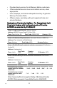
Description of Engines and Essential Requirements Engine Type Fuel Type Combustion Cycle ☒ Outboard engine ☒ Petrol ☒ 2 stroke Identification of Engines Covered by This Declaration of Conformity Name of engine family Unique engine identification number: starting serial number EC Module H certificate number 1.5L OptiMax 75, 80, 90, 115, 125 hp 1B227000 RCD‑H‑2 2.5L OptiMax 135, 150, 175 hp 1B227000 RCD‑H‑2 3.
Name / function: Mark D.
vi eng
WARRANTY INFORMATION Warranty Registration.................................................................. 1 Transfer of Warranty.................................................................... 2 Transfer of Mercury Product Protection (Extended Service Coverage) Plan United States and Canada................................. 2 Outboard Limited Warranty.......................................................... 3 3 Year Limited Warranty Against Corrosion................................
Transporting Trailering Boat/Outboard .......................................................... 43 Fuel and Oil Fuel Recommendations............................................................. 44 Oil Recommendation................................................................. 46 Fuel Additives............................................................................ 46 Fuel Requirements.................................................................... 46 Avoiding Fuel Flow Restriction..............
Maintenance Outboard Care........................................................................... 68 EPA Emissions Regulations...................................................... 68 Inspection and Maintenance Schedule...................................... 69 Flushing the Cooling System..................................................... 71 Top Cowl Removal and Installation........................................... 72 Cleaning Care for Top Cowl......................................................
Troubleshooting Starter Motor Will Not Crank the Engine.................................. 100 Engine Will Not Start................................................................ 100 Engine Runs Erratically........................................................... 101 Performance Loss.................................................................... 101 Battery Will Not Hold Charge................................................... 101 Owner Service Assistance Local Repair Service.......................
Maintainance Log Maintenance Log.....................................................................
xii eng
WARRANTY INFORMATION Warranty Registration UNITED STATES AND CANADA To be eligible for warranty coverage, the product must be registered with Mercury Marine. At the time of sale, the selling dealer should complete the warranty registration and immediately submit it to Mercury Marine via MercNET, e‑mail, or mail. Upon receipt of this warranty registration, Mercury Marine will record the registration. A copy of the warranty registration should be provided to you by your selling dealer.
WARRANTY INFORMATION Transfer of Warranty UNITED STATES AND CANADA The limited warranty is transferable to a subsequent purchaser, but only for the remainder of the unused portion of the limited warranty. This will not apply to products used for commercial applications. To transfer the warranty to the subsequent owner, send or fax a copy of the bill of sale or purchase agreement, new owner’s name, address, and engine serial number to Mercury Marine’s warranty registration department.
WARRANTY INFORMATION To transfer the plan to the subsequent owner, contact Mercury Product Protection or an authorized dealer to receive a Request for Transfer form. Submit to Mercury Product Protection a receipt/bill of sale, a completed Request of Transfer form, and a check payable to Mercury Marine in the amount of $50.00 (per engine) to cover the transfer fee. Plan coverage is not transferable from one product to another product or for non‑eligible applications.
WARRANTY INFORMATION DURATION OF COVERAGE: This Limited Warranty provides coverage for three (3) years from the date the product is first sold to a recreational use retail purchaser, or the date on which the product is first put into service, whichever occurs first. Commercial users of these products receive warranty coverage of one (1) year from the date of first retail sale, or one (1) year from the date on which the product was first put into service, whichever occurs first.
WARRANTY INFORMATION WHAT MERCURY WILL DO: Mercury's sole and exclusive obligation under this warranty is limited to, at our option, repairing a defective part, replacing such part or parts with new or Mercury Marine certified remanufactured parts, or refunding the purchase price of the Mercury product. Mercury reserves the right to improve or modify products from time to time without assuming an obligation to modify products previously manufactured.
WARRANTY INFORMATION WHAT IS NOT COVERED: This limited warranty does not cover routine maintenance items, tune‑ups, adjustments, normal wear and tear, damage caused by abuse, abnormal use, use of a propeller or gear ratio that does not allow the engine to run in its recommended wide‑open throttle RPM range (see the Operation and Maintenance Manual), operation of the product in a manner inconsistent with the recommended operation/duty cycle section of the Operation and Maintenance Manual, neglect, accident,
WARRANTY INFORMATION For additional information regarding events and circumstances covered by this warranty, and those that are not, see the Warranty Coverage section of the Operation and Maintenance Manual, incorporated by reference into this warranty. DISCLAIMERS AND LIMITATIONS: THE IMPLIED WARRANTIES OF MERCHANTABILITY AND FITNESS FOR A PARTICULAR PURPOSE ARE EXPRESSLY DISCLAIMED.
WARRANTY INFORMATION CONDITIONS THAT MUST BE MET IN ORDER TO OBTAIN WARRANTY COVERAGE: Warranty coverage is available only to retail customers that purchase from a Dealer authorized by Mercury Marine to distribute the product in the country in which the sale occurred, and then only after the Mercury Marine specified predelivery inspection process is completed and documented. Warranty coverage becomes available upon proper registration of the product by the authorized dealer.
WARRANTY INFORMATION HOW TO OBTAIN WARRANTY COVERAGE: The customer must provide Mercury with a reasonable opportunity to repair, and reasonable access to the product for warranty service. Warranty claims shall be made by delivering the product for inspection to a Mercury dealer authorized to service the product. If purchaser cannot deliver the product to such a dealer, written notice must be given to Mercury. We will then arrange for the inspection and any covered repair.
WARRANTY INFORMATION Corrosion damage caused by stray electrical currents (onshore power connections, nearby boats, submerged metal) is not covered by this corrosion warranty and should be protected against by the use of a corrosion protection system, such as the Mercury Precision Parts or Quicksilver MerCathode system and/or Galvanic Isolator. Corrosion damage caused by improper application of copper base antifouling paints is also not covered by this limited warranty.
WARRANTY INFORMATION Warranty Coverage and Exclusions The purpose of this section is to help eliminate some of the more common misunderstandings regarding warranty coverage. The following information explains some of the types of services that are not covered by warranty. The provisions set forth following have been incorporated by reference into the Three Year Limited Warranty Against Corrosion Failure, the International Limited Outboard Warranty, and the United States and Canada Limited Outboard Warranty.
WARRANTY INFORMATION 5. Additional service work requested by customer other than that necessary to satisfy the warranty obligation. 6. Labor performed by other than an authorized dealer may be covered only under the following circumstances: when performed on emergency basis (providing there are no authorized dealers in the area who can perform the work required or have no facilities to haul‑out, etc., and prior factory approval has been given to have the work performed at this facility). 7.
WARRANTY INFORMATION 16. Our limited warranty does not apply to any damage to our products caused by the installation or use of parts and accessories which are not manufactured or sold by us. Failures which are not related to the use of those parts or accessories are covered under warranty if they otherwise meet the terms of the limited warranty for that product. U.S.
WARRANTY INFORMATION d. Ignition coil and/or control module e. Ignition wires 4. Lubrication system (4‑Stroke engines excluded) a. Oil pump and internal parts b. Oil injectors c. Oil meter 5. Exhaust system a. Exhaust manifold b. Exhaust valves 6. Miscellaneous items used in above systems a. Hoses, clamps, fittings, tubing, sealing gaskets or devices, and mounting hardware b. Pulleys, belts, and idlers c. Vacuum, temperature, check and time sensitive valves and switches d.
WARRANTY INFORMATION WHAT IS COVERED: Mercury Marine warrants the components of the emissions control systems (see the components listed in the Emission Control System Components) of its new, 2001 model year and later outboards, sold by a California dealer to retail customers residing in California, to be free from defects in material or workmanship, that cause the failure of a warranted part to be identical in all material respects to that part as described in the application of Mercury Marine for certific
WARRANTY INFORMATION HOW TO OBTAIN WARRANTY COVERAGE: The customer must provide Mercury with a reasonable opportunity to repair and reasonable access to the product for warranty service. Warranty claims shall be made by delivering the product for inspection to a Mercury dealer authorized to service the product. If purchaser cannot deliver the product to such a dealer, please notify Mercury Marine and Mercury will then arrange for the inspection and any covered repair.
WARRANTY INFORMATION Expenses related to haul‑out, launch, towing, storage, telephone, rental, inconvenience, slip fees, insurance coverage, loan payments, loss of time, loss of income, or any other type of incidental or consequential damages are not covered by this warranty. Also, expenses associated with the removal and/or replacement of boat partitions or material caused by boat design for access to the product are not covered by this warranty.
WARRANTY INFORMATION California Air Resources Board Explanation of Your California Emission Control Warranty Statement YOUR WARRANTY RIGHTS AND OBLIGATIONS: The California Air Resources Board is pleased to explain the emission control system warranty on your 2001 model year and later outboard engine. In California, new outboard engines must be designed, built, and equipped to meet the State's stringent anti‑smog standards.
WARRANTY INFORMATION As the outboard engine owner, you should, however, be aware that Mercury Marine may deny you warranty coverage if your outboard engine or a part has failed due to abuse, neglect, improper maintenance, or unapproved modifications. You are responsible for presenting your outboard to a Mercury dealer authorized to service the product as soon as a problem exists. The warranty repairs will be completed in a reasonable amount of time, not to exceed 30 days.
WARRANTY INFORMATION Three Stars ‑ Ultra Low Emission 42538 The Three Star label identifies engines that meet the Air Resources Board's Personal Watercraft and Outboard marine engine 2008 exhaust emissions standards or the Sterndrive and Inboard marine engine 2003‑2008 exhaust emission standards. Engines meeting these standards have 65% lower emissions than One Star ‑ Low Emission engines.
GENERAL INFORMATION Boater's Responsibilities The operator (driver) is responsible for the correct and safe operation of the boat and safety of its occupants and general public. It is strongly recommended that each operator (driver) read and understand this entire manual before operating the outboard. Be sure at least one additional person onboard is instructed in the basics of starting and operating the outboard and boat handling in case the driver is unable to operate the boat.
GENERAL INFORMATION Boat Horsepower Capacity ! WARNING Exceeding the boat's maximum horsepower rating can cause serious injury or death. Overpowering the boat can affect boat control and flotation characteristics or break the transom. Do not install an engine that exceeds the boat's maximum power rating. Do not overpower or overload your boat.
GENERAL INFORMATION Outboard Remote Control Models The remote control connected to your outboard must be equipped with a start in neutral only protection device. This prevents the engine from starting when the shift is actuated in any position other than neutral. ! WARNING Starting the engine with the drive in gear can cause serious injury or death. Never operate a boat that does not have a neutral‑safety‑protection device.
GENERAL INFORMATION Choose a propeller for your boating application that will allow the engine to operate within the specified full throttle operating range. When operating the boat at full throttle under normal load conditions, the engine RPM should be in the upper half of the recommended full throttle RPM range. Refer to Specifications. If engine RPM is above that range, select a propeller of increased pitch in order to reduce engine RPM.
GENERAL INFORMATION Diameter ‑ The diameter is the distance across the imaginary circle that is made when the propeller rotates. The correct diameter for each propeller has been predetermined for the design of your outboard. However, when more than one diameter is available for the same pitch, use a larger diameter for heavy boat applications and a smaller diameter for lighter applications. Pitch ‑ The pitch is the theoretical distance, in inches, that a propeller travels forward during one revolution.
GENERAL INFORMATION PROPELLER MATERIAL Most propellers manufactured by Mercury Marine are made from either aluminum or stainless steel. Aluminum is suitable for general purpose use and is standard equipment on many new boats. Stainless steel is over five times more durable than aluminum and typically provides performance gains in acceleration and top end speed due to design efficiencies.
GENERAL INFORMATION ! WARNING Improper fasteners or improper installation procedures can result in loosening or disengagement of the steering link rod. This can cause a sudden, unexpected loss of boat control, resulting in serious injury or death due to occupants being thrown within or out of the boat. Always use required components and follow instructions and torque procedures.
GENERAL INFORMATION The lanyard is a cord usually 122–152 cm (4–5 feet) in length when stretched out, with an element on one end made to be inserted into the switch and a snap on the other end for attaching to the operator. The lanyard is coiled to make its at‑rest condition as short as possible to minimize the likelihood of lanyard entanglement with nearby objects.
GENERAL INFORMATION Important Safety Information: The purpose of a lanyard stop switch is to stop the engine when the operator moves far enough away from the operator's position to activate the switch. This would occur if the operator accidentally falls overboard or moves within the boat a sufficient distance from the operator's position.
GENERAL INFORMATION ! WARNING Avoid serious injury or death from deceleration forces resulting from accidental or unintended stop switch activation. The boat operator should never leave the operator's station without first disconnecting the stop switch lanyard from the operator. Accidental or unintended activation of the switch during normal operation is also a possibility.
GENERAL INFORMATION Protecting People in the Water WHILE YOU ARE CRUISING It is very difficult for a person standing or floating in the water to take quick action to avoid a boat heading in his/her direction, even at slow speed. 21604 Always slow down and exercise extreme caution any time you are boating in an area where there might be people in the water.
GENERAL INFORMATION Passenger Safety Message ‑ Pontoon Boats and Deck Boats Whenever the boat is in motion, observe the location of all passengers. Do not allow any passengers to stand or use seats other than those designated for traveling faster than idle speed. A sudden reduction in boat speed, such as plunging into a large wave or wake, a sudden throttle reduction, or a sharp change of boat direction, could throw them over the front of the boat.
GENERAL INFORMATION BOATS WITH FRONT MOUNTED, RAISED PEDESTAL FISHING SEATS Elevated fishing seats are not intended for use when the boat is traveling faster than idle or trolling speed. Sit only in seats designated for traveling at faster speeds. Any unexpected, sudden reduction in boat speed could result in the elevated passenger falling over the front of the boat. 26783 Wave and Wake Jumping Operating recreational boats over waves and wake is a natural part of boating.
GENERAL INFORMATION ! WARNING Wave or wake jumping can cause serious injury or death from occupants being thrown within or out of the boat. Avoid wave or wake jumping whenever possible. There is another less common hazardous result from allowing your boat to launch off a wave or wake. If the bow of your boat pitches down far enough while airborne, upon water contact it may penetrate under the water surface and submarine for an instant.
GENERAL INFORMATION • • • The boat could move suddenly in a new direction. Such a sharp change in direction can cause occupants to be thrown out of their seats or out of the boat. A rapid reduction in speed. This will cause occupants to be thrown forward, or even out of the boat. Impact damage to the outboard and/or boat. Keep in mind, the most important thing you can do to help reduce injury or impact damage during an impact is control the boat speed.
GENERAL INFORMATION Exhaust Emissions BE ALERT TO CARBON MONOXIDE POISONING Carbon monoxide (CO) is a deadly gas that is present in the exhaust fumes of all internal combustion engines, including the engines that propel boats, and the generators that power boat accessories. By itself, CO is odorless, colorless, and tasteless, but if you can smell or taste engine exhaust, you are inhaling CO.
GENERAL INFORMATION GOOD VENTILATION Ventilate the passenger area, open side curtains or forward hatches to remove fumes. Example of desired air flow through the boat: 21622 POOR VENTILATION Under certain running and/or wind conditions, permanently enclosed or canvas enclosed cabins or cockpits with insufficient ventilation may draw in carbon monoxide. Install one or more carbon monoxide detectors in your boat.
GENERAL INFORMATION 2. Examples of poor ventilation while the boat is moving: a b 21628 a - Operating the boat with the trim angle of the bow too high b - Operating the boat with no forward hatches open (station wagon effect) Selecting Accessories for Your Outboard Genuine Mercury Precision or Quicksilver Accessories have been specifically designed and tested for your outboard. These accessories are available from Mercury Marine dealers. IMPORTANT: Check with your dealer before installing accessories.
GENERAL INFORMATION Know and obey all nautical rules and laws of the waterways. Boat operators should complete a boating safety course. Courses are offered in the U.S.A. by 1) the U.S. Coast Guard Auxiliary, 2) the Power Squadron, 3) the Red Cross, and 4) your state boating law enforcement agency. Inquiries may be made to the Boating Hotline, 1‑800‑368‑5647 or the Boat U.S. Foundation information number 1‑800‑336‑BOAT. Make sure everyone in the boat is properly seated.
GENERAL INFORMATION Watch fallen skiers. When using your boat for waterskiing or similar activities, always keep a fallen or down skier on the operator's side of the boat while returning to assist the skier. The operator should always have the down skier in sight and never back up to the skier or anyone in the water. Report accidents. Boat operators are required by law to file a Boating Accident Report with their state boating law enforcement agency when their boat is involved in certain boating accidents.
GENERAL INFORMATION Models Kilowatts Full throttle RPM range 200 225 250 147 165 184 5000–5750 RPM Idle speed in forward gear 575 ± 25 RPM Number of cylinders 6 Piston displacement 3048 cc (186 in³) Cylinder bore 92.1 mm (3.626 in.) Piston stroke 76.2 mm (3.000 in.) Recommended spark plug Spark plug gap NGK IZFR5G NGK lZFR6J or NGK IZFR6J‑11 (if these plugs are unavailable, use NGK PZFR6H) 0.8 mm (0.031 in.) 1.06 mm (0.042 in.) Standard gearcase ratio 1.
GENERAL INFORMATION Component Identification a g b c h d i e f a - Top cowl b - Bottom cowl c - Water pump indicator hole d - Driveshaft housing e - Anti‑ventilation plate f - Anode plate g - Auxiliary tilt switch h - Transom brackets i - Gearcase j - Cooling water intake holes j 29423 42 eng
TRANSPORTING Trailering Boat/Outboard Trailer your boat with the outboard tilted down in a vertical operating position. If additional ground clearance is required, the outboard should be tilted up using an accessory outboard support device. Refer to your local dealer for recommendations. Additional clearance may be required for railroad crossings, driveways and trailer bouncing.
FUEL AND OIL Fuel Recommendations IMPORTANT: Use of improper gasoline can damage your engine. Engine damage resulting from the use of improper gasoline is considered misuse of the engine, and damage caused thereby will not be covered under the limited warranty. FUEL RATINGS Mercury Marine engines will operate satisfactorily when using a major brand of unleaded gasoline meeting the following specifications: USA and Canada ‑ having a posted pump Octane Rating of 87 (R+M)/2 minimum.
FUEL AND OIL The fuel system components on your Mercury Marine engine will withstand up to 10% alcohol content in the gasoline. We do not know what percentage your boat's fuel system will withstand. Contact your boat manufacturer for specific recommendations on the boat's fuel system components (fuel tanks, fuel lines, and fittings).
FUEL AND OIL Oil Recommendation Recommended Oil Mercury OptiMax/DFI or Quicksilver DFI 2‑Cycle Engine Oil Mercury OptiMax/DFI or Quicksilver DFI 2‑Cycle Engine Oil is recommended for your engine. If Mercury OptiMax/DFI or Quicksilver DFI 2‑Cycle Engine Oil is not available, we recommend using Mercury or Quicksilver TC‑W3 Premium Plus 2‑Cycle Oil. Severe engine damage may result from use of an inferior oil.
FUEL AND OIL • Low permeation hose is USCG Type B1‑15 or Type A1‑15, defined as not exceeding 15/gm²/24 h with CE 10 fuel at 23 °C as specified in SAE J 1527 ‑ marine fuel hose. EPA Pressurized Portable Fuel Tank Requirements The Environmental Protection Agency (EPA) will require portable fuel systems that are produced after January 1, 2011 for use with outboard engines to remain fully sealed (pressurized) up to 34.4 kPa (5.0 psi).
FUEL AND OIL SPECIAL FEATURES OF THE PORTABLE FUEL TANK • The fuel tank has a two‑way valve which allows air to enter the tank as the fuel is drawn to the engine, and also opens to vent to the atmosphere if internal pressure in the tank exceeds 34.4 kPa (5.0 psi). A hissing noise may be heard as the tank vents to the atmosphere. This is normal. • The fuel tank includes a fuel demand valve that prevents pressurized fuel from entering the engine and causing a fuel system overflow or possible fuel spillage.
FUEL AND OIL DIRECTIONS FOR USING THE PRESSURIZED PORTABLE FUEL TANK 1. When installing the fuel tank cap, turn the cap to the right until you hear a click. This signals that the fuel cap is fully seated. A built‑in device prevents overtightening. 2. Open the manual vent screw on top of the cap for operation and cap removal. Close the manual vent screw for transportation. 3. For fuel hoses that have quick disconnects, disconnect the fuel line from the engine or fuel tank when not in use. 4.
FUEL AND OIL 3. Retighten the fill cap. Stop the engine and replace the top cowl. 29424 Filling Fuel Tank ! WARNING Avoid serious injury or death from a gasoline fire or explosion. Use caution when filling fuel tanks. Always stop the engine and do not smoke or allow open flames or sparks in the area while filling fuel tanks. Fill fuel tanks outdoors away from heat, sparks, and open flames. Remove portable fuel tanks from boat to refill them. Always stop engine before refilling tanks.
FEATURES AND CONTROLS Remote Control Features Your boat may be equipped with one of the Mercury Precision or Quicksilver remote controls shown. If not, consult your dealer for a description of the functions and operations of the remote control.
FEATURES AND CONTROLS Warning System The outboard warning system incorporates a warning horn inside the boat. The warning horn may be located inside the remote control or connected to the ignition key switch. b a 27755 a - Horn inside remote control b - Horn connected to ignition key switch WARNING HORN SIGNALS When the key switch is turned to the "ON" position, the horn will turn on for a moment as a test to show the horn is working.
FEATURES AND CONTROLS Warning Horn Function Sound Description Cooling System Problem Continuous Engine Guardian System is activated. Power limit will vary with level of overheat. Shift outboard into neutral and check for a steady stream of water coming out of the water pump indicator hole. If no water is coming out of the water pump indicator hole or flow is intermittent, stop engine and check water intake holes for obstruction.
FEATURES AND CONTROLS If Guardian System has been activated, reduce throttle speed. The problem will need to be identified and corrected, if possible. The system must be reset before the engine will operate at higher speeds. Moving the throttle lever back to the idle position will reset the system. SMARTCRAFT PRODUCT A Mercury SmartCraft System instrument package can be purchased for this outboard.
FEATURES AND CONTROLS Power Trim and Tilt Your outboard has a trim/tilt control called power trim. This enables the operator to easily adjust the position of the outboard by pressing the trim switch. Moving the outboard in closer to the boat transom is called trimming in or down. Moving the outboard further away from the boat transom is called trimming out or up. The term trim generally refers to the adjustment of the outboard within the first 20° range of travel.
FEATURES AND CONTROLS The most significant control hazard is a pull or torque that can be felt on the steering wheel or tiller handle. This steering torque results from the outboard being trimmed so the propeller shaft is not parallel to the water surface. ! WARNING Trimming the outboard beyond a neutral steering condition may result in a pull on the steering wheel or tiller handle and loss of boat control. Maintain control of the boat if trimming beyond a neutral steering condition.
FEATURES AND CONTROLS • In rare circumstances, the owner may decide to limit the trim in. This can be accomplished by purchasing a stainless steel tilt pin from your dealer and inserting it in whatever adjustment hole in the transom brackets is desired. The nonstainless steel shipping bolt should not be used in this application other than on a temporary basis. 2.
FEATURES AND CONTROLS MANUAL TILTING If the outboard cannot be tilted using the power trim/tilt switch, the outboard can be manually tilted. NOTE: The manual tilt release valve must be tightened before operating the outboard to prevent the outboard from tilting up during reverse operation. Turn out the manual tilt release valve three turns counterclockwise. This allows manual tilting of the outboard. Tilt the outboard to the desired position and tighten the manual tilt release valve.
FEATURES AND CONTROLS AUXILIARY TILT SWITCH This switch can be used to tilt the outboard up or down using the power trim system.
OPERATION Pre‑Starting Check List • • • • • • • • • • • Operator knows safe navigation, boating, and operating procedures. An approved personal flotation device of suitable size for each person aboard and readily accessible (it is the law). A ring type life buoy or buoyant cushion designed to be thrown to a person in the water. Know the boat's maximum load capacity. Look at the boat capacity plate. Fuel supply OK. Oil supply (oil injection) OK.
OPERATION Operating in Saltwater or Polluted Water We recommend that you flush the internal water passages of your outboard with fresh water after each use in salt or polluted water. This will prevent a buildup of deposits from clogging the water passages. Refer to Maintenance ‑ Flushing the Cooling System. If you keep your boat moored in the water, always tilt the outboard so the gearcase is completely out of water (except in freezing temperatures) when not in use.
OPERATION Engine Break‑In Procedure IMPORTANT: Failure to follow the engine break‑in procedures can result in poor performance throughout the life of the engine and can cause engine damage. Always follow break‑in procedures. GASOLINE/OIL BREAK-IN MIXTURE NOTE: Do not use premixed gas and oil during break‑in. Use straight gasoline during engine break‑in and after engine break‑in. The engine break‑in procedure for an OptiMax outboard is important to ensure proper performance and maximum life from the engine.
OPERATION 2. For the next three hours of operation, change engine speed every ten minutes. Starting the Engine Before starting, read the pre‑starting check list, special operating instructions, and engine break‑in procedure in the Operation section. NOTICE Without sufficient cooling water, the engine, the water pump, and other components will overheat and suffer damage. Provide a sufficient supply of water to the water inlets during operation. 1. Lower the outboard to the vertical operating position.
OPERATION 3. Position the fuel line primer bulb so the arrow on the side of the bulb is pointing up. Squeeze the fuel line primer bulb several times until it feels firm. 27348 4. Set the lanyard stop switch to the "RUN" position. Refer to General Information ‑ Lanyard Stop Switch. 19791 5. Shift outboard to the neutral ("N") position. N 26838 6. For the initial start of a new engine, or for an engine that ran out of fuel or was drained of fuel, the fuel system should be filled as follows: a.
OPERATION c. Turn the ignition key switch back to the "OFF" position, and squeeze the primer bulb again until it feels firm. Turn the ignition key switch to the "ON" position again for three seconds. Continue this procedure until the fuel line primer bulb stays firm. 7. Do not advance the throttle‑only feature on the remote control for starting. 27242 8. Turn the ignition key to "START" position. Release the key when engine starts.
OPERATION IMPORTANT: If no water is coming out of the water pump indicator hole, stop engine and check cooling water intake holes for obstruction. No obstruction may indicate a water pump failure or blockage in the cooling system. This condition will cause the engine to overheat. Have the outboard checked by your dealer. Operating the engine while overheated will cause engine damage. 19805 Gear Shifting IMPORTANT: Observe the following: • Never shift outboard into gear unless engine speed is at idle.
OPERATION Stopping the Engine Reduce engine speed and shift outboard to neutral position. Turn ignition key to "OFF" position.
MAINTENANCE Outboard Care To keep your outboard in the best operating condition, it is important that your outboard receive the periodic inspections and maintenance listed in the Inspection and Maintenance Schedule. We urge you to keep it maintained properly to ensure the safety of you and your passengers, and retain its dependability. Record maintenance performed in the Maintenance Log at the back of this book. Save all maintenance work orders and receipts.
MAINTENANCE EMISSION CERTIFICATION LABEL An emission certification label, showing emission levels and engine specifications directly related to emissions, is placed on the engine at the time of manufacture. EMISSION CONTROL INFORMATION a THIS ENGINE CONFORMS TO CALIFORNIA AND U.S.
MAINTENANCE • • • • • Inspect the outboard for tightness to the boat transom. If any looseness of the outboard or mounting fasteners exist, retorque the outboard mounting fasteners to 75 Nm (55 lb‑ft). Check the outboard for tightness on transom. Check the steering system for binding or loose components. Visually check the steering link rod fasteners for proper tightness. See Steering Link Rod Fasteners. Check the propeller blades for damage.
MAINTENANCE • • • Check the power trim fluid. See Checking Power Trim Fluid. Inspect the battery. See Battery Inspection. • Lubricate the splines on the driveshaft and shift shaft.1. Check tightness of bolts, nuts, and other fasteners. Check cowl seals to make sure seals are intact and not damaged. Check internal cowl sound reduction foam (if equipped) to make sure foam is intact and not damaged. Check that the intake silencer (if equipped) is in place.
MAINTENANCE 1. Remove the plug from fitting in the bottom cowl. 29444 2. Attach a water hose to the fitting. Turn on the water and flush for 3 to 5 minutes. 29445 Top Cowl Removal and Installation REMOVAL 1. Release the front and side cowl latches. 2. Lift the top cowl from the outboard. 29447 INSTALLATION 1. Position the top cowl over the engine. 2. Ensure the bottom rubber seal fits properly and lock the front and side latches.
MAINTENANCE CLEANING AND WAXING PROCEDURE 1. Before washing, rinse the top cowl with clean water to remove the dirt and dust that may scratch the surface. 2. Wash the top cowl with clean water and a mild non‑abrasive soap. Use a soft clean cloth when washing. 3. Dry thoroughly with a soft clean cloth. 4. Wax the surface using a non‑abrasive automotive polish (polish designed for clear coat finishes). Remove the applied wax by hand using a clean soft cloth. Alternator Belt Inspection 1.
MAINTENANCE Fuel System ! WARNING Fuel is flammable and explosive. Ensure that the key switch is off and the lanyard is positioned so that the engine cannot start. Do not smoke or allow sources of spark or open flame in the area while servicing. Keep the work area well ventilated and avoid prolonged exposure to vapors. Always check for leaks before attempting to start the engine, and wipe up any spilled fuel immediately.
MAINTENANCE Installation 1. Lubricate the O‑ring seals with oil. a b c 29599 a - Filter b - O‑ring seals c - Link rod 2. Install the fuel filter and tighten securely. 3. Reconnect the link rod. IMPORTANT: Visually inspect for fuel leakage from the filter while squeezing the primer bulb until firm, forcing fuel into the filter. DRAINING WATER FROM THE FUEL FILTER CHAMBER NOTE: If a sufficient amount of water has accumulated in the fuel filter chamber, the warning system will turn on.
MAINTENANCE 3. Retighten the drain screw and reattach the hose. b a c 24607 a - Drain hose b - Side fitting c - Drain screw IMPORTANT: Visually inspect for fuel leakage from the drain screw by squeezing the primer bulb until firm, forcing fuel into the chamber.
MAINTENANCE ! WARNING Improper fasteners or improper installation procedures can result in loosening or disengagement of the steering link rod. This can cause a sudden, unexpected loss of boat control, resulting in serious injury or death due to occupants being thrown within or out of the boat. Always use required components and follow instructions and torque procedures.
MAINTENANCE Fuse Replacement ‑ 200 and 225 HP Models IMPORTANT: Always carry spare 5 and 20 amp fuses. The electrical wiring circuits on the outboard are protected from overload by fuses in the wiring. If a fuse is blown, try to locate and correct the cause of the overload. If the cause is not found, the fuse may blow again.
MAINTENANCE Open the fuse holder and look at the silver colored band inside the fuse. If the band is broken, replace the fuse with a new fuse of the same rating.
MAINTENANCE The electrical wiring circuits on the outboard are protected from overload by fuses in the wiring. If a fuse is blown, try to locate and correct the cause of the overload. If the cause is not found, the fuse may blow again. Open the fuse holder and look at the silver colored band inside the fuse. If the band is broken, replace the fuse with a new fuse of the same rating.
MAINTENANCE The gearcase has three anodes. Two anodes are located on each side of the gearcase, and a third is an anode plate installed underneath the anti‑ventilation plate. If a trim tab should be installed, this anode plate will be removed. Another anode is installed on the bottom of the transom bracket assembly.
MAINTENANCE Battery Information ! WARNING Failure to properly secure the battery leads can result in a loss of power to the Digital Throttle and Shift (DTS) system, leading to serious injury or death due to loss of boat control. Secure the battery leads to the battery posts with hex nuts to avoid loose connections. • • Do not use deep‑cycle batteries. Engines must use a marine starting battery with 1000 MCA, 800 CCA, or 180 Ah.
MAINTENANCE Propeller Replacement ! WARNING Rotating propellers can cause serious injury or death. Never operate the boat out of the water with a propeller installed. Before installing or removing a propeller, place the drive unit in neutral and engage the lanyard stop switch to prevent the engine from starting. Place a block of wood between the propeller blade and the anti‑ventilation plate. 1. Shift outboard to neutral (N) position.
MAINTENANCE 3. Straighten the bent tabs on the propeller nut retainer. 26900 4. Place a block of wood between gearcase and propeller to hold propeller and remove propeller nut. 26901 5. Pull propeller straight off shaft. If propeller is seized to the shaft and cannot be removed, have the propeller removed by an authorized dealer. 6. Coat the propeller shaft with Quicksilver or Mercury Precision Lubricants Anti‑Corrosion Grease or 2‑4‑C with PTFE.
MAINTENANCE Tube Ref No. Description Where Used Part No. 94 Anti-Corrosion Grease Propeller shaft 92-802867Q 1 95 2-4-C Marine Lubricant with PTFE Propeller shaft 92-802859A 1 IMPORTANT: To prevent the propeller hub from corroding and seizing to the propeller shaft (especially in saltwater), always apply a coat of the recommended lubricant to the entire propeller shaft at the recommended maintenance intervals and also each time the propeller is removed. 7.
MAINTENANCE 9. Place a block of wood between gearcase and propeller and torque propeller nut to specifications. Description Nm Propeller nut 75 lb. in. lb. ft. 55 10. Secure propeller nut by bending three of the tabs into the thrust hub grooves. 26945 Spark Plug Inspection and Replacement ! WARNING Damaged spark plug boots may emit sparks which can ignite fuel vapors under the engine cowl, resulting in serious injury or death from a fire or explosion.
MAINTENANCE 2. Remove the spark plugs to inspect. Replace spark plug if electrode is worn or the insulator is rough, cracked, broken, blistered, or fouled. 26946 3. Set the spark plug gap to specification. 26947 Spark Plug Gap 200/225 hp 0.80 mm (0.031 in.) 250 hp 1.06 mm (0.042 in.) 4. Before installing spark plugs, clean off any dirt on the spark plug seats. Install plugs finger‑tight, and then tighten 1/4 turn or torque to specifications. Description Nm Spark plug 27 lb. in. lb. ft.
MAINTENANCE 2. Remove the hose cable tie and pull the air filter off the hose. f a b c d e 28732 abcdef- Air filter Nylon washer Rubber washer Clamp Filter housing Cable tie INSTALLATION 1. Place the nylon washer and rubber washer onto the air filter and insert the filter into the housing. Rotate the filter 1/4 turn to the lock position. 2. Position the filter housing so the inlet hose is facing towards the back of the engine. Reinstall the hose and secure with a cable tie.
MAINTENANCE 3. Secure the filter housing with the clamp. a b c d 28738 abcd- Air filter Filter housing Clamp Inlet hose Lubrication Points 1. Lubricate the following with Quicksilver or Mercury Precision Special Lubricant 101. Tube Ref No. 34 eng Description Special Lubricant 101 Where Used Part No.
MAINTENANCE • Trim rod ball ends ‑ Turn the ball ends to work the lubricant into the ball sockets. 28458 2. Lubricate the following with Quicksilver or Mercury Precision Lubricants Anti‑Corrosion Grease or 2‑4‑C with PTFE. Tube Ref No. Description Where Used Part No. 94 Anti-Corrosion Grease Propeller shaft 92-802867Q 1 95 2-4-C with PTFE Propeller shaft 92-802859A 1 • Propeller shaft ‑ Refer to Propeller Replacement for removal and installation of the propeller.
MAINTENANCE Tube Ref No. 95 Description 2-4-C with PTFE Where Used Part No. Alternator belt tensioner pivot shaft, swivel bracket, tilt support lever, tilt tube, steering cable 92-802859A 1 • Alternator belt tensioner pivot shaft ‑ Lubricate through fitting. 2884 • Swivel bracket ‑ Lubricate through fitting. • Tilt support lever ‑ Lubricate through fitting.
MAINTENANCE • Tilt tube ‑ Lubricate through fitting. 27874 ! WARNING Incorrect cable lubrication can cause hydraulic lock, leading to serious injury or death from loss of boat control. Completely retract the end of the steering cable before applying lubricant. • Steering cable ‑ Rotate steering wheel to fully retract the steering cable end into the outboard tilt tube. Lubricate through fitting. a b a - Fitting b - Cable end 27875 4. Lubricate the following with lightweight oil.
MAINTENANCE Checking Power Trim Fluid 1. Tilt outboard to the full up position and engage the tilt support lever. 27877 2. Remove fill cap and check fluid level. The fluid level should be even with the bottom of the fill hole. Add Quicksilver or Mercury Precision Lubricant Power Trim and Steering Fluid. If not available, use automotive automatic transmission fluid (ATF). 28460 Tube Ref No. 114 eng Description Power Trim and Steering Fluid Where Used Part No.
MAINTENANCE Gearcase Lubrication When adding or changing gearcase lubricant, visually check for the presence of water in the lubricant. If water is present, it may have settled to the bottom and will drain out prior to the lubricant, or it may be mixed with the lubricant, giving it a milky colored appearance. If water is noticed, have the gearcase checked by your dealer. Water in the lubricant may result in premature bearing failure or, in freezing temperatures, will turn to ice and damage the gearcase.
MAINTENANCE CHECKING LUBRICANT LEVEL AND REFILLING GEARCASE 1. Place outboard in a vertical operating position. 2. Remove vent plug/sealing washer. 3. Remove fill/drain plug. Place lubricant tube into the fill hole and add lubricant until it appears at the vent hole. a b 22693 a - Vent hole b - Fill hole IMPORTANT: Replace sealing washers if damaged. 4. Stop adding lubricant. Install the vent plug and sealing washer before removing the lubricant tube. 5.
STORAGE Storage Preparation The major consideration in preparing your outboard for storage is to protect it from rust, corrosion, and damage caused by freezing of trapped water. The following storage procedures should be followed to prepare your outboard for out of season storage or prolonged storage (two months or longer). NOTICE Without sufficient cooling water, the engine, the water pump, and other components will overheat and suffer damage.
STORAGE 3. Pull the drain hose off the right side fitting. Hold the open end of the hose over a container. 4. Loosen drain screw and drain the fuel filter chamber. a - Drain screw b - Drain hose c - Right side fitting a c b 23751 5. Retighten the drain screw and reattach the hose. 6. Pull the drain hose off the left side fitting. Hold the open end of the hose over a container. 7. Loosen the drain screw and drain the float chamber. a - Left side fitting b - Drain screw c - Drain hose a b c 23752 8.
STORAGE 10. Remove the fuel filter. See Maintenance ‑ Fuel System for procedure. 11. Pour this mixture into the fuel filter opening. Reinstall the fuel filter. 12. Prime the fuel system. See Operation ‑ Starting The Engine. 13. Place the outboard in water or use the flush hose or flushing device or for circulating cooling water. Start the engine and run at idle speed for five minutes to allow the treated fuel to fill the fuel system.
STORAGE • • Touch up any paint nicks. See your dealer for touch‑up paint. Spray Quicksilver or Mercury Precision Lubricants Corrosion Guard on external metal surfaces (except corrosion control anodes). Tube Ref No. 120 Description Corrosion Guard Where Used Part No. External metal surfaces 92-802878 55 Gearcase • Drain and refill the gearcase lubricant (refer to Gearcase Lubrication).
TROUBLESHOOTING Starter Motor Will Not Crank the Engine POSSIBLE CAUSES • Blown 20 amp fuse in the starting circuit. Refer to Maintenance. • Outboard is not shifted to neutral position. • Weak battery or battery connections are loose or corroded. • Ignition key switch failure. • Wiring or electrical connection faulty. • Starter motor solenoid or slave solenoid failure. Engine Will Not Start POSSIBLE CAUSES • Lanyard stop switch not in "RUN" position. • Battery not fully charged.
TROUBLESHOOTING Engine Runs Erratically POSSIBLE CAUSES • Spark plugs fouled or defective. Refer to Maintenance section. • Incorrect setup and adjustments. • Fuel is being restricted to the engine. a. Engine fuel filter is obstructed. Refer to Maintenance section. b. Fuel tank filter obstructed. c. Stuck antisiphon valve on built‑in fuel tank. d. Fuel line is kinked or pinched. e. Injector plugged. • Threaded connection of an air hose is loose. • Fuel pump failure. • Ignition system component failure.
OWNER SERVICE ASSISTANCE Local Repair Service Always return your outboard to your local authorized dealer should the need for service arise. Only he has the factory trained mechanics, knowledge, special tools, equipment, and genuine parts and accessories to properly service your engine should the need occur. He knows your engine best. Service Away from Home If you are away from your local dealer and the need arises for service, contact the nearest authorized dealer.
OWNER SERVICE ASSISTANCE • • • • • Your name and address Daytime telephone number Model and serial number of your outboard The name and address of your dealership Nature of problem Mercury Marine Service Offices For assistance, call, fax, or write. Please include your daytime telephone number with mail and fax correspondence. United States, Canada Telephone English ‑ (920) 929‑5040 Français ‑ (905) 636‑4751 Fax English ‑ (920) 929‑5893 Français ‑ (905) 636‑1704 Website www.mercurymarine.
OWNER SERVICE ASSISTANCE Asia, Singapore Telephone (65) 65466160 Fax (65) 65467789 Brunswick Asia Pacific Group T/A Mercury Marine Singapore Pte Ltd 29 Loyang Drive Singapore, 508944 104 eng
OUTBOARD INSTALLATION Important Information BEFORE STARTING THE ENGINE NOTICE Lack of oil pressure in the system can cause severe internal engine damage during start‑up. Prime the oil injection pump on new or rebuilt engines or after performing maintenance on the oiling system. Refer to Priming the Oil Injection Pump for instructions. FUEL REQUIREMENTS Do not use premixed gas and oil in this engine. The engine automatically receives extra oil during engine break‑in.
OUTBOARD INSTALLATION Boat Horsepower Capacity ! WARNING Exceeding the boat's maximum horsepower rating can cause serious injury or death. Overpowering the boat can affect boat control and flotation characteristics or break the transom. Do not install an engine that exceeds the boat's maximum power rating. Do not overpower or overload your boat.
OUTBOARD INSTALLATION Some accessories not manufactured or sold by Mercury Marine are not designed to be safely used with this outboard or outboard operating system. Acquire and read the installation, operation, and maintenance manuals for all selected accessories. Fuel System AVOIDING FUEL FLOW RESTRICTION IMPORTANT: Adding components to the fuel supply system (filters, valves, fittings, etc.) may restrict the fuel flow.
OUTBOARD INSTALLATION FUEL DEMAND VALVE (FDV) REQUIREMENT Whenever a pressurized fuel tank is used, a fuel demand valve is required to be installed in the fuel hose between the fuel tank and primer bulb. The fuel demand valve prevents pressurized fuel from entering the engine and causing a fuel system overflow or possible fuel spillage. The fuel demand valve has a manual release. The manual release can be used (pushed in) to open (bypass) the valve in case of a fuel blockage in the valve.
OUTBOARD INSTALLATION 3. Turn the ignition key switch back to the "OFF" position, and squeeze the primer bulb again until it feels firm. Turn the ignition key switch to the "ON" position again for three seconds. Continue this procedure until the fuel line primer bulb stays firm. Installation Specifications a a b 18552 a - Minimum transom opening b - Engine centerline for dual engine ‑ 66.0 cm (26 in.) Minimum Transom Opening Single engine 84.8 cm (33‑3/8 in.) Dual engine 151.8 cm (59‑3/4 in.
OUTBOARD INSTALLATION 2. Thread the lifting eye into the flywheel hub for a minimum of five turns. a a - Lifting eye 28495 3. Connect a hoist to the lifting eye. 4. Lift the outboard and place it on the boat transom. Lifting Eye 91‑90455‑‑1 Threads into the flywheel to remove the powerhead assembly from the driveshaft housing, or to lift entire engine for removal/installation. 2756 Steering Cable ‑ Starboard Side Routed Cable 1. Lubricate O‑ring seal and entire cable end. 95 3724 Tube Ref No.
OUTBOARD INSTALLATION 2. Insert steering cable into tilt tube. 3725 3. Torque nut to specification. 3727 Description Nm Nut 47.5 lb‑in. lb‑ft 35 Steering Link Rod Fasteners IMPORTANT: The steering link rod that connects the steering cable to the engine must be fastened using a special washer head bolt (P/N 10‑849838) and self‑locking nylon insert locknuts (P/N 11‑826709113).
OUTBOARD INSTALLATION ! WARNING Improper fasteners or improper installation procedures can result in loosening or disengagement of the steering link rod. This can cause a sudden, unexpected loss of boat control, resulting in serious injury or death due to occupants being thrown within or out of the boat. Always use required components and follow instructions and torque procedures. ! WARNING Worn, loose, or seized steering components can lead to loss of boat control.
OUTBOARD INSTALLATION 2. Assemble the steering link rod to the engine with the special washer head bolt "a" and self‑locking nylon insert locknut "b." 3. Torque the head bolt, then the locknut to specifications. Description Nm Cable coupler nylon insert locknut "d" eng lb‑in. lb‑ft Tighten locknut until it seats, then loosen ¼ turn.
OUTBOARD INSTALLATION Determining Recommended Outboard Mounting Height 63.5 cm (25 in.) e 60.9 cm (24 in.) b c 58.4 cm (23 in.) 56.0 cm (22 in.) a 53.3 cm (21 in.) 50.8 cm (20 in.) e d 48.2 cm (19 in.
OUTBOARD INSTALLATION NOTICE 1. The outboard should be mounted high enough on the transom so the exhaust relief hole will stay at least 25.4 mm (1 in.) above the waterline when the engine is running at idle speed. Having the exhaust relief hole above the waterline will prevent exhaust restrictions. Exhaust restrictions will result in poor performance at idle. 2. Add 12.7 cm (5 in.) for XL models to the listed outboard mounting heights. 3. The mounting height of the outboard must not exceed 63.
OUTBOARD INSTALLATION Transom Drilling Fixture 91‑98234A2 Aids in engine installation by acting as a template for engine mounting holes. 5489 2. Drill four 13.5 mm (17/32 in.) mounting holes. 3973 Fastening the Outboard to the Transom MOUNTING BOLTS Outboard Transom Mounting Hardware ‑ Supplied with Outboard Part Number Part Name Description 10‑8M0033366 Transom bolt 1/2‑20 x 5.00 in. long (3.25 in. thread) 11‑826711‑17 Nylon insert locknut 1/2‑20 12‑28421 Washer ‑ Inner 0.516 in. ID x 1.
OUTBOARD INSTALLATION Available Outboard Mounting Bolts Part Number Description 10‑67755‑003 ½‑20 x 5.50 in. long (3.25 in. thread) 10‑67755‑2 ½‑20 x 6.50 in. long (2.75 in. thread) 10‑8M0028080 ½‑20 x 7.50 in. long (2.75 in. thread) 10‑8M0032860 ½‑20 x 8.00 in. long (2.75 in. thread) CHECKING BOAT TRANSOM CONSTRUCTION IMPORTANT: Determine the strength of the boat transom.
OUTBOARD INSTALLATION Use a dial torque wrench to determine transom strength. If the bolt or nut continues to turn without the torque reading on the dial increasing, it is an indication the transom is yielding. The load area can be increased by using a larger washer or a transom reinforcement plate. a b 33962 a - Large transom washer b - Transom reinforcement plate 1. Apply marine sealer to the shanks of the bolts, not to the threads. 2. Fasten the outboard with the correct mounting hardware.
OUTBOARD INSTALLATION NOTE: For more accurate torque, tighten the mounting locknuts rather than the outboard mounting bolts. d c a e b c a d 40952 abcde- eng 1/2 in. diameter outboard mounting bolt (4) 7/8 in. flat washer (4) Nylon insert locknut (4) 1‑1/2 in.
OUTBOARD INSTALLATION Electrical, Hoses, Control Cables, and Front Clamp REMOTE WIRING HARNESS Route the remote 14 pin boat harness through the front clamp opening in the bottom cowl. Connect remote harness to the 14 pin connector on the engine harness. a 28742 a - 14 pin connector BATTERY INFORMATION ! WARNING Failure to properly secure the battery leads can result in a loss of power to the Digital Throttle and Shift (DTS) system, leading to serious injury or death due to loss of boat control.
OUTBOARD INSTALLATION IMPORTANT: Battery cable size and length is critical. Refer to engine installation manual for size requirements. The decal needs to be placed on or near the battery box for future service reference. One 5/16 in. and one 3/8 in. hex nut is supplied per battery for wing nut replacement. Metric hex nuts are not supplied.
OUTBOARD INSTALLATION Dual Outboards Connect a common ground cable (wire size same as engine battery cables) between negative (–) terminals on starting batteries. a b a b c (-) (-) d d 15497 abcd- Red sleeve ‑ Positive (+) Black sleeve ‑ Negative (–) Ground cable Cranking battery HOSE AND TUBING CONNECTIONS Fuel Hose The minimum fuel line inside diameter (I.D.) is 8 mm (5/16 in.), with a separate fuel line/fuel tank pickup for each engine.
OUTBOARD INSTALLATION Water Pressure and Speedometer Hose or Tubing NOTE: This applies to models without SmartCraft gauges. This outboard has a speedometer water pickup located in the leading edge of the gearcase. If you want to use this water pickup for the speedometer, disconnect the water pickup tubing from the speedometer sensor and route tubing out of the cowl. Install the coupler provided with the outboard on the end of the tubing.
OUTBOARD INSTALLATION Make the water pressure gauge hose connection to the tubing as shown.
OUTBOARD INSTALLATION INSTALLING THE SHIFT CABLE IMPORTANT: The shift cable is the first cable to move when the remote control handle is moved out of neutral, so install/connect it to the engine first. Locating the Center Point of the Shift Cable IMPORTANT: Locate the center point of the slack or lost motion that exists in the shift cable for proper adjustment of the shift cable. 1. Mark the forward position as follows: a.
OUTBOARD INSTALLATION c. Place a mark on the shift cable against the cable end guide. a 29077 a - Reverse position mark 3. Mark the center on the shift cable midway between the forward and reverse marks. a 4361 a - Center mark 4. Align the cable end guide against this center mark when installing the cable to the engine. 5. Position the remote control and outboard into neutral position. 6.
OUTBOARD INSTALLATION Adjusting the Shift Cable 1. Align the shift cable end guide with the center mark as instructed in Locating the Center Point of the Shift Cable. a 4362 a - Center mark 2. Place the shift cable end guide on the anchor pin and adjust the cable barrel so that it slips freely into the barrel holder. 3. Secure the shift cable to the anchor pin with the retainer clip. a c b 28749 a - Cable barrel b - Shift cable retainer c - Retainer clip 4.
OUTBOARD INSTALLATION c. Shift the remote control into reverse while turning the propeller shaft. If the propeller shaft does not lock solidly in gear, adjust the barrel away from the cable end guide. Repeat steps a through c. d. Return the remote control handle to neutral. If the propeller shaft does not turn freely without drag, adjust the barrel closer to the cable end guide. Repeat steps a through d.
OUTBOARD INSTALLATION 3. Adjust the cable barrel so the installed throttle cable will hold the idle stop screw against the stop. c a b 28751 a - Barrel sleeve b - Cable barrel c - Idle stop screw 4. Check the throttle cable adjustment as follows: a. Shift the outboard into gear a few times to activate the throttle linkage. Rotate the propeller shaft while shifting into reverse. b. Return the remote control to neutral. c. Place a thin piece of paper between the idle adjustment screw and the idle stop.
OUTBOARD INSTALLATION 5. Lock the barrel holder in place with the cable latch. 2682 FRONT CLAMP ASSEMBLY INSTALLATION IMPORTANT: There must be sufficient slack in the engine wiring harness, battery cables, fuel hose, and oil hoses, between clamp and engine attachment point, to relieve stress and prevent hoses from being kinked or pinched. 1. Place the lower half of the front clamp into the bottom cowl opening. 2.
OUTBOARD INSTALLATION 3. Join the top half of the front clamp with the bottom half. Secure both halves together with cables ties. a 29074 b a - Top half of the front clamp b - Cable ties 4. Secure the front clamp into the bottom cowl with the retainer and two screws. 5. Install the cowl seal.
OUTBOARD INSTALLATION Oil Injection Set‑Up FILLING OIL SYSTEM 1. Fill remote oil tank with the recommended oil listed in the Operation and Maintenance Manual. Tighten fill cap. a a - Fill cap 2683 2. Remove cap and fill engine oil tank with oil. Reinstall the fill cap.
OUTBOARD INSTALLATION PRIMING OIL INJECTION PUMP Before starting the engine for the first time, prime the oil injection pump. Priming will remove any air that may be in the pump, oil supply hose, or internal passages. b a 3768 a - Oil supply hose b - Oil injection pump IMPORTANT: Fill the engine fuel system with fuel before priming the oil injection pump. Otherwise, the fuel pump will run without fuel during the priming process and may be damaged. 1. Fill the fuel system. a. Connect fuel hose. b.
OUTBOARD INSTALLATION d. Turn the ignition key switch to the "ON" position for three seconds. This operates the electric fuel pump. 26846 e. Turn the ignition key switch back to the "OFF" position, and squeeze the primer bulb again until it feels firm. f. Turn the ignition key switch to the "ON" position again for three seconds. g. Continue this procedure until the fuel primer bulb stays firm. 2. Turn the ignition key switch to the "ON" position. 3.
OUTBOARD INSTALLATION Trim In Pin ! WARNING Operating the boat at high speeds with the outboard trimmed too far under can create excessive bow steer, resulting in the operator losing control of the boat. Install the trim limit pin in a position that prevents excessive trim under and operate the boat in a safe manner. Some boats, particularly some bass boats, are built with a greater than normal transom angle, which will allow the outboard to be trimmed further in or under.
OUTBOARD INSTALLATION The owner may decide to limit the trim in. This can be accomplished by purchasing a stainless steel tilt pin from your dealer and insert it in whatever adjustment hole in the transom brackets is desired. A nonstainless steel shipping bolt should not be used in this application other than on a temporary basis.
MAINTAINANCE LOG Maintenance Log Record all maintenance performed on your outboard here. Be sure to save all work orders and receipts.