ASSEMBLY INSTRUCTION ASSEMBLY INSTRUCTION ASSEMBLY TIPS: 1.Remove hardware from box and sort by size. 2.Please check to sae that all hardware and parts are present prior to start of assembly. 3. Pleass follow attached instructions in the same sequence as numbered to assure fast & easy assembly. A Warning! 1.Don't attempt to repair or modify parts that are broken or defective. Please contact the store immediately. 2.This product is for home use only and not intended for commercial establishment.
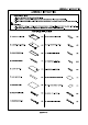
ASSEMBLY INSTRUCTION PCS (3) UPPER BOTTOM PANEL SEAT SIDE PANEL (T)} UPPER CROSS PANEL 2pcg | (Y) SEAT BOTTOM PANEL (V) UPPER BACK PANEL <> 1PC | (AB) SEAT BAG DIVIDER PANEL (MORROW PC | (AC) SEAT CUSHION {J) UPPER TOP PANEL Ry 1PC | (AA) SEAT FRONT DIVIDER PANEL PC Zz HARDWARE PACKAGE NO| DESCRIPTION FIGURE QTY |[NO| DESCRIPTION FIGURE QTY 1 | Gluey 1PC | 8 | HANDLE L=120mm CAM BOLT §7x35.
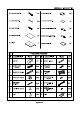
ASSEMBLY INSTRUCTION z HARDWARE PACKAGE NO| DESCRIPTION FIGURE QTY |[NO| DESCRIPTION FIGURE QTY 15 HINGE SCREW § 4x15mm PIPE THREAD §6.2x45mm 17 | ‘presser SS PCS | 22 | RING BOX =, PC FIXER SCREW 16 arcs | 21 PCS PCS | 20 | FIXER Ie PCs ~£ § 3x18mm 18 METAL PLATE 4.5x12 3x1.
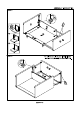
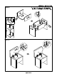
ASSEMBLY INSTRUCTION STEP 2 The Glue (1) should be used in the indicated locations to help solidify the assembled unit.
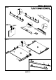
ASSEMBLY INSTRUCTION STEP 4 The Glue (1) should be used in the indicated locations to help solidify the assembled unit.
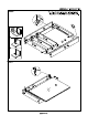
ASSEMBLY INSTRUCTION STEP 6 The Glue (1) should be used in the indicated locations to help solidify the assembled unit.
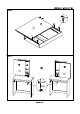
ASSEMBLY INSTRUCTION STEP 10 Detail #2 on © STEP 11 The Glue (1) should be used in the indicated locations to help solidify the assembled unit. \ Jk ya INCORRECT
ASSEMBLY INSTRUCTION The Glue (1) should be used in the indicated locations to help solidify the assembled unit.
ASSEMBLY INSTRUCTION STEP 14 The Glue (1) should be used in the indicated Fn Vans locations to help solidify the assembled unit.
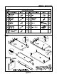
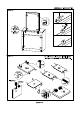
ASSEMBLY INSTRUCTION Assembly Instruction as below: Step 1: Insert (2) into the holes at two sides of + Insert (2) into the holes at top side of » Insert (3) into the holes on the * Nail (6) at bottom of » then (10-CL) on (A) » (10-CR) on (B) by (11). Step 2: Connect with (A) » when (3) is connected inside (4) + tightly fasten (4) clockwise. Insert (G) on and between along slots. Apply the same technique to connect with (B).