
Installation Instructions


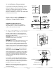
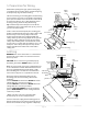
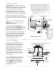
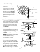
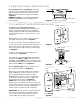
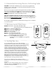
Table Of Contents

page 7
9. Light Kit Assembly (Optional). (cont.)
If you do NOT wish to use the light kit, locate slots
on metal cover and align with nodules inside LED
light kit. Push up on metal cover and turn to the
RIGHT (clockwise) until it no longer turns. [Refer to
diagram 3.]
WARNING: Do NOT connect the male and female
plugs for the LED light kit if you do NOT wish to
use the light kit.
metal cover
diagram 3
10. Assembly of Handheld Remote Control.
IN ORDER TO USE THE HANDHELD REMOTE
CONTROL, PLEASE CONTINUE WITH SECTION 10 for
remote control assembly instructions. If you have
already installed the wall control but do not wish to
use the handheld remote control, please proceed to
Section 11.
Gently pull on remote control cover to separate
top and bottom parts. [Refer to diagram 1.]
In order to use wall control as a handheld remote
control, cut each wire on wall control (that was not
previously used)--use wire cutters to cut off each
wire as close to the wall control as possible. [Refer
to diagram 2.]
Install one 12-volt battery (included) in wall
control. [Refer to diagram 2.]
Since this fan comes with LED bulbs, the dimmer
switch (labeled DIM and ON) has been pre-set to
the "ON" position (DIM). If you do not wish to have
dimming capability, please move the switch to the
"OFF" position (ON). [Refer to diagram 2.]
Attach black faceplate to front of wall control;
press down firmly. [Refer to diagram 3.]
Align holes in wall control with posts located on
inside of TOP part of remote control cover and
press together firmly. Place wall control into
BOTTOM part of remote control cover, aligning
posts in top of remote control cover with post
holes in the bottom. [Refer to diagram 3.]
(NOTE: Make sure to align narrower ends of
remote control cover before closing.) Squeeze top
and bottom of remote control cover together until
you hear a click at each end, indicating that the
remote control cover has closed completely.
IMPORTANT: Store the remote control away from
excess heat or humidity. To prevent damage to
remote control, remove the battery if remote
control will not be used for long periods.
(top)
(bottom)
remote control
cover
diagram 1
diagram 2
diagram 3
dimmer
switch
wall control
wire
wire
wire
12V battery
11
-
22
-
DIM ON
11
-
22
-
DIM ON
wall
control
face-
plate
remote control
cover, BOTTOM
post
hole
post
hole
remote control
cover, TOP