Assembly Instructions P.
General Assembly Guidelines I. Ensure that all parts and hardware are available before beginning assembly. II. Follow each step carefully to ensure the proper assembly of this product. III. Two people are recommended for ease in the assembly of this product. IV. V. The three main types of hardware used to assemble this product are : wood dowels , screws and bolts. The provided glue is to secure wood dowels in place .
Parts List 1 18 17 9 20 19 15 3 x4 16 10 14 7 8 6 5 14 2 11 12 13 12 13 12 12 11 4 P.
Hardware List A Ø8x30mm Wooden dowel 18 pcs B Ø6x35mm Cam bolt 30 pcs C Ø15x11mm Cam lock 10 pcs D Ø15x9mm Cam lock 20 pcs E Ø30mm Sticker 30 pcs F Ø6x50mm Screw 8 pcs G Ø6x12mm Bolt 20 pcs H M4 Hex key 1 pc Shelf support pin 8 pcs Screw 26 pcs L Bolt 4 pcs M Pulley 4 pcs N Pulley 4 pcs Screw 10 pcs Plastic wedge 10 pcs J K P Ø4x32mm Ø3x17mm Q R Ø4x12mm Screw 2 pcs S Ø4x25mm Screw 2 pcs T Plastic strap 2 pcs U Nut 2 pcs V
Step 1 Slider arm Y Slider arm Slider bracket Y Slider bracket Pick up the slider arm (Y) and separate the slide Runner for the following Steps. Extend the Slide .Runner all the way forward,press the plastic release lever of the alider arm up and pull the Slide Runner Complete out . P.
Step 2 W W W Y W 18 W W Y 16 x4 Using screw (W) attach drawer slider (Y) to parts (16,18) with Philips head screwdriver as per diagram. P.
Step 3 6 8 W W W Y W W W W W Y W W W W W Y W W W W Y W W Y Y W W W W Y Y W Using screw (W) attach drawer slider (Y) to parts (6,8) with Philips head screwdriver as per diagram. P.
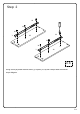
Step 4 B B B B B B 1 B B B 15 B B x4 Secure cam bolt (B) into parts (1,15) with Philips head screwdriver as per diagram. P.
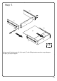
Step 5 18 K 16 17 18 K 19 17 16 x4 Using screw (K) attach parts (16,18) to part (17) with Philips head screwdriver as per diagram. Put part (19) as per diagram. P.
1 Step 6 2 18 3 D D 15 20 D 16 20 K 17 x4 Using screw (K) attach part (17) to part (20), then using cam lock (D) secure part (15) into parts(16, 18,20) with Philips head screwdriver as per diagram. P.
Step 7 A A A A A A A A A 6 8 7 5 4 B B A A A A A A A A A Insert wooden dowel (A) into parts (4,5,6,7,8), then secure cam bolt (B) into parts (6,8) with Philips head screwdriver as per diagram. P.
1 Step 8 2 3 8 4 C Using cam lock (C) secure part (8) to part (4) with Philips head screwdriver as per diagram. P.
1 Step 9 2 3 6 4 C Using cam lock (C) secure part (6) to part (4) with Philips head screwdriver as per diagram. P.
Step 10 5 6 8 7 2 F H Using screw (F) attach part (2) into parts (5,6,7,8) with hex key (H) as per diagram. P.
Step 11 12 12 2 13 12 13 G 12 H Using bolt (G) attach parts (12,13) to part (2) with Hex key (H) as per diagram. P.
Step 12 9 5 3 7 10 2 Put parts (3,9,10) as per diagram. P.
1 Step 13 2 3 1 C C C C C C C 8 7 C 6 5 Using cam lock (C) secure part (1) into parts (5,6,7,8) with Philips head screwdriver as per diagram. P.
Step 14 3 K K Q P Q Secure screw (K), then using screw (P) secure plastic wedge (Q) with Philips head screwdriver as per diagram. P.
Step 15 E E E E E E E x4 Place sticker (E) cover the holes as per diagram . P.
Step 16 8 J J 5 J 7 J J 6 J 11 J J 11 J 11 J Insert shelf support pin (J) into parts (5,6,8,9) as per diagram. Make sure you place the four shelf support pins (J) in the same level. So the shelf is not titled .Put part (11) into unit as per diagram. Tilt and rest the adjustable shelf(11) onto the shelf support pins . P.
Step 17 x2 M 14 M W W M L W N L W N W L N W Secure screw (L) into part (14), then using screw (W) attach pulley (M,N) with Philips head screwdriver as per diagram. P.
Step 18 1 M M 1 14 14 2 N 2 Pick up the door (14), and fit the pulley (N) over the slider rails on the bottom panel (2) ,then place the pulley (M) into top panel (1) , till it click into pulley as per diagram. P.
Step 19 Slider arm Y Slider bracket x4 Insert the assembled drawers into the unit frame, extend the Ball Bearing Slide Tracks (Y) on the pedestal Side Panel all the way forward .Then align the Slide Runners on the assembled drawers with the Slide Tracks and push the drawer carefully inside until it stops. Note : if the drawer does not go in smoothly, please take it out and repeat the step.
Step 20 Position the assembled unit at the desired location ,if necessary adjust the floor leveler at the bottom of the leg to level the unit . P.
Step 21 1 T R Using screw (R) attach Velcro strap (T) into part (1) with Philips head screwdriver as per diagram. P.
1 Step 22 2 3 WARNING Serious or fatal injuries can occur from furniture tipping over. To prevent the furniture from tipping over we recommend that it is permanently fixed to the wall. Wall anchor and hardware are included with this product. Please make sure hardware is suitable for your walls before installing, as different wall materials may require different types of anchors. Wall U S T Using screw (S) attach Velcro strap (T) into Nut (U) to wall with Philips head screwdriver as per diagram. P.
Step 23 Final Assembly P.