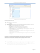
PureWave Quantum 6600 User Guide v2.1 Figure 106: Service Profile HARQ Profile The main grouping sections are: Key settings. This simply displays: o Profile # Hybrid ARQ Profile. This displays all that the available configuration parameters . These are: o Name. This is the profile name and it is a text field o Description. This is the profile description and it is a text field. o Enable. This is a check box to enable/disable the HARQ profile. o Channel-mapping. This is the HARQ Map Length.
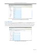
PureWave Quantum 6600 User Guide v2.1 Figure 107: Service Profile HARQ Profile Edit Capability 3.5.5.3 ARQ Profile At Main Web GUI Interface Screen select the Configuration Tab, then the service-profile Main Menu option and then the arq-profile Main Menu Sub-Element. This User is presented with all the 3 preconfigured default profiles. To physically view all the profile configuration parameters then the User must actually select a profile and two main grouping sections are presented (refer to Figure 108).
PureWave Quantum 6600 User Guide v2.1 The main grouping sections are: Key settings. This simply displays: o Profile # ARQ Profile. This displays all that the available configuration parameters. These are: o Name. This is the profile name and it is a text field o Description. This is the profile description and it is a text field. o Enable. This is a check box to enable/disable the ARQ profile. o Deliver-in-order. This is a check box to enable/disable the ARQ deliver in order option. o Window-size.
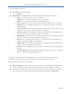
PureWave Quantum 6600 User Guide v2.1 Figure 109: Service Profile ARQ Profile Edit Capability 3.5.5.4 Quality of Service, QoS Profile A QoS Profile contains all information in regards to QoS type, latency, throughput and etc. These Profiles are independent of direction and can be applied to multiple service flows. The types of QoS that are offered are: Best Effort or BE. Alternatively this is described as MIR or Maximum Information Rate. Unsolicited Grant Service or UGS.
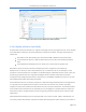
PureWave Quantum 6600 User Guide v2.1 not being requested by the Subscriber, the allocated eRTPS bandwidth can be used by any other Subscriber. The eRTPS is the preferred QoS type for VoIP applications due to the dynamic resource control. There are 16 QoS profiles that have been pre-configured and stored in the Base Station. These can be viewed at the summary level (refer to Figure 110). At Main Web GUI Interface Screen select the Configuration Tab and then select the service-profile Main Menu Sub-Element.
PureWave Quantum 6600 User Guide v2.1 Figure 111: Quality of Service Profiles The main grouping sections are: Key settings. This simply displays: o Profile # QoS Profile. This displays all that the available configuration parameters. These are: o Name. This is the profile name and it is a text field. o Description. This is the profile description and it is a text field. o Max-sustained-traffic-rate. This is a Maximum Sustained Traffic Rate. This is assigned in bits per second in the range 0 to 4294967295.
PureWave Quantum 6600 User Guide v2.1 o Unsolicited-poll-interval. This is a Unsolicited Poll Interval. This is assigned as a number in the range 0 to 65535. The System is pre-configured with 16 default profiles. If the User wants to add any of their configurations, they must delete a profile before they can add and configure a new one. When in Edit mode, the User is presented with (refer to Figure 112): .
PureWave Quantum 6600 User Guide v2.1 Figure 113: Client Profile The main grouping sections are: Key settings. This simply displays: o Profile # ARQ Profile. This displays all that the available configuration parameters. These are: o Description. This is the profile description and it is a text field. o Max-dl-rate. This is a Maximum Downlink Rate that is reserved for this client. This is assigned in bits per second in the range 0 to 4294967295. o Max-pps. This is a Maximum Packets per second.
PureWave Quantum 6600 User Guide v2.1 o o o o o o Description. This is the text description of the Client profile. Direction. This is the direction of the traffic flow. Arq-profile-num. This is the number of the arq profile that has been assigned for this Client Profile. Cls-profile-num. This is the number of the classifier profile that has been assigned for this Client Profile. Harq-profile-num. This is the number of the harq profile that has been assigned for this Client Profile. Qos-profile-num.
PureWave Quantum 6600 User Guide v2.1 User navigates to the red icon then this will present the User with the ability to delete the profile. Figure 115: Client Profile Edit Full Capability The main grouping sections are: Key settings. This simply displays: o Profile # Service Flow Profile. This displays all that the available configuration parameters. These are: o Name. This is the Service Flow name and it is a text field. o Description. This is the Service Flow description and it is a text field.
PureWave Quantum 6600 User Guide v2.1 3.6 Base Station Software Upgrade One of the Base Stations’ key features is that it has been designed to support a “Software Defined Radio” (SDR) architecture. The distinct advantage is that a Base Station can be remotely upgraded with additional features and capabilities as these are developed. The Base Station maintains two software versions/images that may be selectively enabled, thus providing a fail-safe software upgrade procedure.
PureWave Quantum 6600 User Guide v2.1 Figure 117: FTP Server Configuration At the Main Web GUI Interface Screen select the Configuration Tab and then the software Main Menu Option. This will display the software Settings and the display is split into two main grouping sections. There are three further sub-element associated with this option. There are no User configurable options for the software Main Menu Option. The Base Station flash contains two partitions which are both loaded with software.
PureWave Quantum 6600 User Guide v2.1 Figure 118: Software Image Management Dialog 3.6.1 Single-Step Software Upgrade The Base Station software upgrade process can be performed using a single operation. This performs the following procedure while providing continual upgrade status to the User. (1) (2) (3) (4) (5) Downloads the software image file from a user defined location using FTP, HTTP, or HTTPS.
PureWave Quantum 6600 User Guide v2.1 user:password@ is optional, and the :password part can be omitted [:port] is also optional Examples using ftp (you can substitute http or https): ftp://myhost.com/filename ftp://myhost.com/directory/filename ftp://myhost.com:2323/directory/filename ftp://myname@myhost.com:2323/directoryname/filename ftp://myname:password@myhost.
PureWave Quantum 6600 User Guide v2.1 (3) Automatically reboot the Base Station. The reboot will then automatically be loaded from the next boot partition which was changed in step (2) above. This means that the Base Station will now be operational on the software that was just downloaded. 3.6.2 Multi-Step Software Upgrade The Base Station software upgrade process can also be performed in multiple steps as an alternative to the single step process.
PureWave Quantum 6600 User Guide v2.1 protocol://[user[:password]]@host[:port]/path protocol can be ftp, http, or https Figure 120: Software Download and Installation Dialog Once the URL has been entered, the User must select the Perform Command Menu Option in the Download Software Images, install, select and reboot on Base Station section to initiate the upgrade process. This action will upgrade the Base Station in one simple step.
PureWave Quantum 6600 User Guide v2.1 Figure 121: Software Partition Selection and Display The purpose of the Select Next SW Image to Boot from is that this command will allow the selected image to run after the next reboot. It will not affect the currently "Running" image. Subsequent reboots will run the "Select" software image. The available choices are: A: The image loaded in software bank A. B: The image loaded in software bank B. Next: The alternative to the currently "Running " image.
PureWave Quantum 6600 User Guide v2.1 Figure 122: Software Image Partition Selection To execute the procedure then the User needs to select the Perform Command Menu Option in the Select Next SW Image to Boot from grouping section. If the "Now" box is checked (i.e. enabled) the system will reboot shortly after the Perform Command Menu Option has been selected. It may take up to a minute for the Base Station to reboot.
PureWave Quantum 6600 User Guide v2.1 3.6.3 Base Station Performance Monitoring There are a number of monitoring parameters that can be checked to determine the overall performance of the Base Station and for any Subscribers that are connected to the Base Station. These parameters are contained within a variety of menu options. The User’s starting point is Web GUI Main Web GUI Interface Screen. 3.6.3.
PureWave Quantum 6600 User Guide v2.1 Interface Settings and Status. The configured settings and their current status that are displayed for the five interfaces are: o Admin State. This is the admin state. o Oper State. This is the operational state. o Link Speed. This is the interface link speed. o Duplex Type. This is duplex setting. o Maximum MTU Length. This is the maximum configured MTU Length. o MAC Address. This is the MAC address of the interface.
PureWave Quantum 6600 User Guide v2.1 Configuration Tab, then the interface Main Menu Option, then the status Main Menu Sub-Element and then relevant interface. At the Main Web GUI Interface Screen select the Configuration Tab and then the interface Main Menu Option, then the configure main Menu Sub-Element. The resulting window will be split into two main sections (refer to Figure 124). 3.6.3.
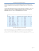
PureWave Quantum 6600 User Guide v2.1 Figure 126: Sector Statistics Interface Key Settings The further sub-elements are: service-flow-metrics. Several key service flow metrics are provided at a sector level (i.e. a Base Station level). packer-error-rate-metrics. This will display several key packet error rate counters. startup-counters. These are startup counters for a sector level. throughput-counters. Sector throughput counters are displayed.
PureWave Quantum 6600 User Guide v2.1 o o o o o o o DSC Requests DSC Req Successes DSD Requests DSD Req Successes Max Active Svc Flows Max Active DL Svc Flows Max Active UL Svc Flows Figure 127: Sector Statistics Interface Key Settings A similar format is repeated for the other three sector, statistics sub elements. The Key Settings window indicates the relevant sector.
PureWave Quantum 6600 User Guide v2.
PureWave Quantum 6600 User Guide v2.1 Figure 129: Sector Statistics Startup Counters Figure 130: Sector Statistics Throughput Counters Important Subscriber statistics are contained within the statistics-mss Main Menu Sub-Element within the Sector Main Menu Option. The User now has to navigate to the next level, therefore at the Main Web GUI Interface Screen select the sector Main Menu Option and then the statistics-mss Main Menu Sub-Element.
PureWave Quantum 6600 User Guide v2.1 Figure 131: Sector MSS-Statistics Metrics The further sub-elements are: mss-throughput-counters. This is the throughput counters for the Subscribers that are communicating with the Base Station. sflow-throughput-counters. These are the throughput counters per service flow. rssi-cinr-counters. These are the RSSI and CINR metrics per Subscriber and per upstream/ downstream direction. harq-counters. These are the HARQ counters per Subscriber. modulation-code-rate.
PureWave Quantum 6600 User Guide v2.1 At the Main Web GUI Interface Screen select the Configuration Tab and then the sector Main Menu Option, then the statistics-mss Main Menu Sub-Element and then mss-throughput-counters. There are two distinct groups to this window (refer to Figure 132). Key Settings. This indicates the relevant Subscriber. This is not a configurable parameter. The following information is presented: o Sector o MAC Address Throughput Counters Per MSS. The following Metrics are displayed.
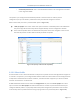
PureWave Quantum 6600 User Guide v2.1 Key Settings. This indicates the relevant Subscriber. This is not a configurable parameter. The following information is presented: o Sector o MAC Address o SFID. This is the Service Flow identifier. Throughput Counters Per Service-Flow. The following Metrics are displayed. These are displayed as a raw number but they can also be displayed in graphical form by selecting the "Graph" command button.
PureWave Quantum 6600 User Guide v2.1 Downstream RSSI/CINR Metrics. The following Metrics are displayed. These are displayed as a raw number but they can also be displayed in graphical form by selecting the "Graph" command button. If the CLI is used to view metrics, the RSSI per antenna will be shown but will have the same value across all antennas. o CINR Mean o CINR Std Dev o RSSI Mean o RSSI Std Dev Upstream RSSI/CINR Metrics. . The following Metrics are displayed.
PureWave Quantum 6600 User Guide v2.1 Figure 135 Sector Statistics Upstream RSSI CINR Metrics At the Main Web GUI Interface Screen select the Configuration Tab and then the sector Main Menu Option, then the statistics-mss Main Menu Sub-Element and then harq-counters. There will be three HARQ Service Flow identifiers displayed for each Subscriber. There are two distinct groups to this window (refer to Figure 136). Key Settings. This indicates the relevant Subscriber. This is not a configurable parameter.
PureWave Quantum 6600 User Guide v2.1 o o o HARQ UL Pkt Retrans HARQ UL Pky Discards HARQ UL Pkt 1st Neg Ack Figure 136: Sector Statistics HARQ Counters At the Main Web GUI Interface Screen select the Configuration Tab and then the sector Main Menu option, then the statistics-mss Main Menu Sub-Element and then modulation-code-rate. The information for each Subscriber is displayed. There are two distinct groups to this window (refer to Figure 137). Key Settings. This indicates the relevant Subscriber.
PureWave Quantum 6600 User Guide v2.1 Figure 137: Sector Statistics Modulation Code Counters At the Main Web GUI Interface Screen select the Configuration Tab and then the sector Main Menu Option, then the statistics-mss Main Menu Sub-Element and then active-service-flows. The Service Flows that are active for each Subscriber will be displayed. For each Subscriber there will be at least two active Service Flows, one for Upstream and another for Downstream.
PureWave Quantum 6600 User Guide v2.1 Figure 138: Sector Statistics Active Service Flows At the Main Web GUI Interface Screen select the Configuration Tab and then the sector Main Menu Option, then the statistics-mss Main Menu Sub-Element and then registered-ss. The number of registered Subscribers will be displayed. There are two distinct groups to this window (refer to Figure 139). Key Settings. This indicates the relevant Subscriber. This is not a configurable parameter.
PureWave Quantum 6600 User Guide v2.1 Figure 139: Sector Statistics Registered SS 3.6.3.3 Logging The Base Station contains a number of internal system management logs. The Web Gui provides the User with complete flexibility on performing a number of key actions on these logs. At the Main Web GUI Interface Screen select the Configuration Tab and then select the logging Main Menu Option. This will display all the system logs files (Figure 140).
PureWave Quantum 6600 User Guide v2.1 The logging Main Menu option contains four Main Menu Sub-Elements. These are: remote. The User has the capability to define a remote server to forward a pre-defined log level. local. The User has the capability to define the minimum severity level to log. file. These are file actions that the User can perform. files. This describes the system log files.
PureWave Quantum 6600 User Guide v2.1 Figure 141: Logging Remote Host Information At the Main Web GUI Interface Screen select the Configuration Tab and then select the logging Main Menu Option and then the local Main Menu Sub-Element. The User is now presented with a window that displays the local Log Server Settings. This only one distinct group to this window (refer to Figure 142). The User can select to view the relevant details. Default Local Log Server Settings.
PureWave Quantum 6600 User Guide v2.1 Figure 142: Logging Local Information At the Main Web GUI Interface Screen select the Configuration Tab, then select the logging Main Menu option, then the local Main Menu Sub-Element and then override. The User can now is now presented with an option to increase or decrease the internal sys log per daemon/application which are internal to the Base Station (refer to Figure 143). The User must be in Edit mode to configure.
PureWave Quantum 6600 User Guide v2.1 When in Edit mode only one distinct group to this window is displayed. The User must and define the relevant App Name. The configurable options are: Key Settings App Name o confd o wmdlpcClientd o r6mgrd o sectord o statsd o genactiond o snmpactiond o gpsmgrsyncd o swumgrd o sysmgrd Once the App Name has been selected then the User is presented with an Application Log Settings menu where the Severity Level can be configured.
PureWave Quantum 6600 User Guide v2.1 This will force a reboot of the Base Station and the log file to effectively rotate and begin logging again. The rotate feature forces the logging to the relevant file to stop, it then compresses the file, effectively renames it (generally by appending a .1 to the end of the filename) and then starts the logging to a new file. E.g. the current sys log file is messages but at the last rotate action this file was rotated into messages.1.
PureWave Quantum 6600 User Guide v2.1 Figure 146: Logging File Delete At the Main Web GUI Interface Screen select the Configuration Tab, then select the logging Main Menu Option, then the file Main Menu Sub-Element and then upload. This option provides a means for the User to upload a log file to a server URL. Two distinct window groups are presented to the User. These are (refer to Figure 147): Upload Log File to Remote Server. This simply provides a description of the actions. Upload Log File.
PureWave Quantum 6600 User Guide v2.1 ftp://myname@myhost.com:2323/directoryname/filename ftp://myname:password@myhost.com:2323/directoryname/filename URL of remote source file; format is as follows: protocol://[user[:password]]@host[:port]/path protocol can be ftp, http, or https Figure 147: Logging File Upload At the Main Web GUI Interface Screen select the Configuration Tab, then select the logging Main Menu option, and then the files main Menu Sub-Element.
PureWave Quantum 6600 User Guide v2.1 If the User selects a relevant file, then the characteristics of the file are displayed. The following information will be displayed for each file (refer to Figure 149): Key Settings o Filename System Log Files o Size. This is the file size in bytes. o Modified. This was the date that the file was last modified.
PureWave Quantum 6600 User Guide v2.1 3.6.3.4 SNMP Server Simple Network Management Protocol (SNMP) is an "Internet-standard protocol for managing devices on IP networks. The SNMP server exposes management data in the form of variables on the managed systems, which describe the system configuration (MIBs). These variables can then be queried and set by managing applications called Network Management Systems (NMS).
PureWave Quantum 6600 User Guide v2.1 Figure 151 Community sub-menu If the User wants to add or edit any of the existing community strings then they must then select enter the Edit Mode (Edit Private or Edit Exclusive). The following options will be available for each entry (Figure 152) Key Settings o SNMP Community Index snmpCommunityEntry o SNMP Community Name. Name of the community string o SNMP Community Security Name.
PureWave Quantum 6600 User Guide v2.1 Figure 152 snmpCommunityEntry Table The user sub-menu (Figure 153 and Figure 154) allows the protection of SNMPv3 packets from the above threats by utilizing a concept of multiple users where each user provides secret keys for authentication and privacy. If the User wants to add or edit any of the existing user record then they must then select user and enter the Edit Mode (Edit Private or Edit Exclusive).
PureWave Quantum 6600 User Guide v2.1 Figure 153 SNMP user configuration Figure 154 SNMP user configuration continued The notify sub-menu (Figure 155) configures the SNMP notification generation mechanism. If the User wants to add or edit any of the existing community strings then they must then select snmpNotifyTable and enter the Edit Mode (Edit Private or Edit Exclusive).
PureWave Quantum 6600 User Guide v2.1 Figure 155 SNMP Notify Configuration Name Description Field Example Snmp Notify Name A unique identifier used to index this table 1-32 chars Snmp Notify Tag A tag value used to reference one or more entries in snmpTargetAddrTable.
PureWave Quantum 6600 User Guide v2.1 Figure 156 SNMP Trap Destination The trap destination sub-menu (Figure 156) specifies the network and transport layer attributes of notification destinations. Each row in this table is used to send traps to a different NMS. If the User wants to add or edit any of the existing trap destinations, then they must then select NMSAddress and enter the Edit Mode (Edit Private or Edit Exclusive).
PureWave Quantum 6600 User Guide v2.
PureWave Quantum 6600 User Guide v2.1 Name snmpTargetAddrName Description Name of the target snmpTargetAddrTable snmpTargetAddrTDomain This object indicates the transport type of the address contained in the snmpTargetAddrTAddress object snmpTargetAddrTAddress Specifies the target address, which consists of an IP address followed by a UDP port number snmpTargetAddrTimeout Sets a timeout value (in ticks) for the transmission of InformRequest PDU or TCP connection.
PureWave Quantum 6600 User Guide v2.1 3.6.3.5 Alarm Management The Quantum Base Station has advanced alarm and fault management capabilities. When a fault or event occurs, an alarm condition will be raised. An alarm is a persistent indication of a fault that clears only when the triggering condition has been resolved. To configure Alarm Management, select the Configuration Tab and then select the alarm Main Menu Option (Figure 159).
PureWave Quantum 6600 User Guide v2.
PureWave Quantum 6600 User Guide v2.1 Appendix A Capacity Tables We present here a set of tables specifying the raw (MAC-layer) throughput of a PureWave Quantum Family base Station for 5, 7 and 10MHz, under ideal conditions, corresponding to the maximum achievable performance that can be achieved using IEEE 802.16e per channel bandwidth and TDD configuration ratio. All results assume PUSC, a MAP size of 4 symbols, and 1 preamble symbol.
PureWave Quantum 6600 User Guide v2.1 MCS Rate 64QAM-5/6 64QAM-3/4 64QAM-2/3 64QAM-1/2 16QAM-3/4 16QAM-1/2 QPSK-3/4 QPSK-1/2 MCS Rate 64QAM-5/6 64QAM-3/4 64QAM-2/3 64QAM-1/2 16QAM-3/4 16QAM-1/2 QPSK-3/4 QPSK-1/2 Downlink 10MHz Uplink Bi-Dir Downlink 17.28 8.40 25.68 8.64 15.55 7.56 23.11 7.78 13.82 6.72 20.54 6.91 10.37 5.04 15.41 5.18 10.37 5.04 15.41 5.18 6.91 3.36 10.27 3.46 5.18 2.52 7.70 2.59 3.46 1.68 5.14 1.73 Table 16: Max Throughput – 29:18 - 62%:38% 5MHz Uplink Bi-Dir 4.08 3.67 3.26 2.
PureWave Quantum 6600 User Guide v2.1 MCS Rate Downlink 7MHz Uplink Bi-Dir 6.7 15.4 64QAM-5/6 8.6 6.0 13.8 64QAM-3/4 7.8 5.4 12.3 64QAM-2/3 6.9 4.0 9.2 64QAM-1/2 5.2 2.7 6.1 16QAM-3/4 3.5 2.0 4.6 16QAM-1/2 2.6 1.7 1.3 3.1 QPSK-3/4 8.6 6.7 15.
PureWave Quantum 6600 User Guide v2.1 Appendix B Limited Warranty Statements Hardware PureWave, Inc (“PureWave” or the “Company”) warrants to the original end-user (“Customer”) that this hardware product will conform in all material respects to the specifications provided with the hardware and will be free from defects in workmanship and materials, under normal use and service, for a period of 365 days from the date of original shipment by PureWave.
PureWave Quantum 6600 User Guide v2.1 Additional Conditions Notwithstanding anything else herein or otherwise, PureWave reserves the right to establish amendments to its RMA Policy from time to time. Further, PureWave Technical Support may prefer to troubleshoot the wireless link with an onsite Customer technician while the Products are in their original non-conforming state. This process might assist Customer in understanding and troubleshooting the issue.
PureWave Quantum 6600 User Guide v2.1 Obtaining Warranty Service Customer must contact the Company, by sending an e-mail to support@pwnets.com to obtain warranty service authorization. When contacting PureWave for support, please be prepared to provide the product description and serial number and a description of the problem. The Customer will be expected to complete a “Return Material Authorization (RMA)” form to initiate the request.
PureWave Quantum 6600 User Guide v2.