
Quick Start Guide


Designed for Operators, by Operators
56 | P a g e
configured minus 28. Example 1: If the Maximum distance is set to 13Km, the area of coverage
will be between the Base Station up to 13Km. Example 2: If the Maximum distance is set to
44Km, the area of coverage will be between 16Km and 44Km. We recommend configuring
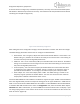
this value appropriately such that the desired area is covered. When applying the change, a
popup will appear and you will be required to commit (Figure 50).
• Noise and Interference Settings. The default is 35. NI is defined as per the IEEE 802.16-e as
the noise per tone in 0.5 db steps above the -150 dBm, where 0 is -150dbm and 35 is -
132.5dbm per tone. This value represents the noise level per tone at the receiver of the Base
station which gets advertised and is used by the CPEs to determine their uplink TX power
when operating in open loop power control.
• Auto Noise Level Adjustment Support. Enables the automatic dynamic adjustment of NI and
internal settings with respect to the measured noise level on the channel. The Noise
measurement values can be seen in the radio tab.
• DL ECINR Report Support. Specifies the mode of CINR reporting to be provided from the CPEs.
Default is enabled (ECINR). Disabling CINR reporting should be done only in case of older CPE
revisions that do not support ECINR reporting.
• UCD Interval. This is WiMAX 802.16e UCD Interval value and it is to be defined in milliseconds.
Interval defined in milliseconds. The default is 1000 (1 second) and the available range is 15 up
to 10000.
• 5MHz Large Map Support – Available and applicable only in case of 5MHz channel bandwidth
setting. Extends the MAP size and supports larger number of bursts per frame. Recommended
to be enabled in case of large number of CPEs and when using combined data + voice.
To view the Radio Settings, at the Main Web GUI Interface Screen select the Configuration Tab, select
sector Main Menu Option, advanced Main Menu Sub-Element, 1, and then radio. The display is split into
three main grouping sections. These sections do not fit onto one screen and therefore the User must
scroll down to view etc (refer to Figure 51 and Figure 52).
• Radio Settings (configured). These are the parameters that the User can Edit
• Radio Settings (state). These are the current configurations values of the parameters
• Noise and Interference Measurements (status). These are the current configurations values of
the parameters. The Noise level is represented in 3 different measurement units
Figure 50 Distance Setting Warning Pop-up