
Quick Start Guide


Designed for Operators, by Operators
10 | P a g e
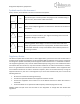
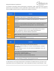
The function of each Base station connector/port is described in Table 1. Note that every connector
present must be terminated to ensure proper Base station operation. Please refer to the Mercury
Quantum 6600 Installation Guide for comprehensive installation procedures.
Connector
Function
Power
-48VDC power source inputs for the unit. DC power connector: LTW
BB-04PMMS-LC7001 (chassis), LTW BB-04BFFA-LL7001 (mate)
GPS
N-type female connector for mandatory external GPS antenna. 3.3V power on
center pin.
ETH-1
This Gigabit Ethernet port serves as the data traffic backhaul Interface and also
provides for in-band management of the Base Station. Available port options are
Cat-5 (RJ-45), Single-Mode Fiber (HartingPull/Han 3 A), and Multi-Mode (LC
duplex) Fiber.
ETH-2
This Gigabit Ethernet port may be used for out-of-band management of the Base
Station. It may also be used to connect to an external device, such as a web
camera. Available port options are Cat-5 (RJ45), Single-Mode Fiber
(HartingPull/Han 3 A), and Multi-Mode (LC duplex) Fiber.
Console
RJ-45 based RS-232 port for CLI control via a console. Defaults settings are
38400, 8 data bits, 1 stop bit, no parity bits, no flow control.
ANT 1-6
N-type Tx / Rx Antenna Ports.
Table 1 Base Station Connector Description
LED
Function
Status
Green - BS is up and running normally. No faults detected.
Blinking Red – System booting up, or system is temporarily down. Solid Red -
Fault detected.
Off – LEDs disabled or Power is off. Fault detected if POWER LED is Green, but
STATUS LED is Off.
Link
(Status LED for ETH-1 Gigabit Ethernet Port) Solid Green
– Connected to an Ethernet switch.
Blinking Green – Ethernet packet activity.
Off – LEDs disabled or no Ethernet activity detected.
Power
Green – Power is being supplied to the BS.
Off – LEDs disabled or no power is being supplied to the BS.
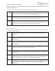
Table 2 Base Station LED Description
The Base Station’s three high-intensity LEDs are intended to be viewable from the ground for quick
confirmation of the unit’s operational state. Table 2 describes the function of each indicator. Note